|
Pietenpol
Project
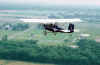
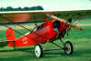
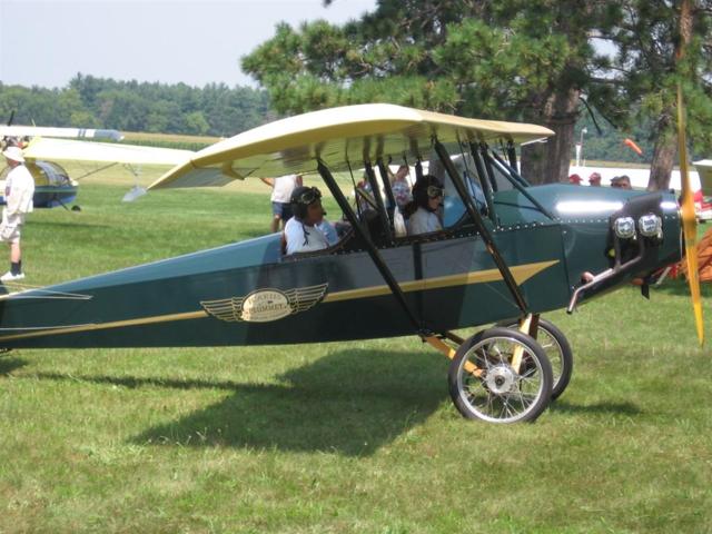
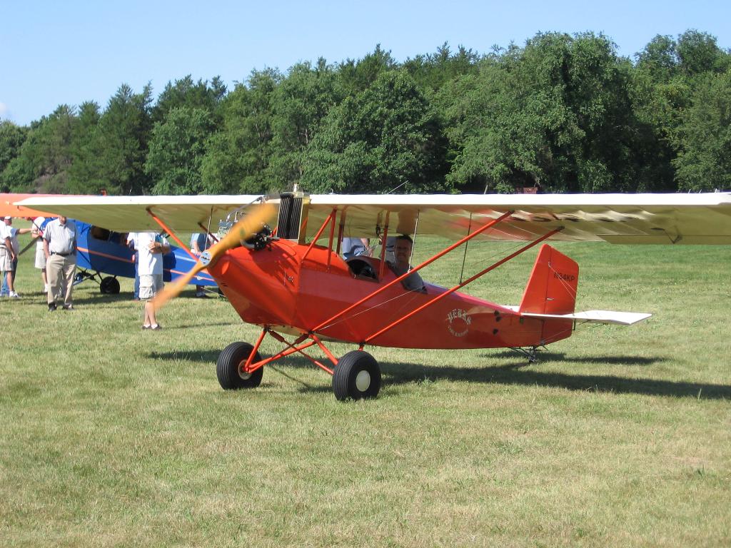
What the heck is a Pietenpol? It's a 1930 open
cockpit designed by Bernard Pietenpol. It is a two place, wood and fabric
ship that cruises about 65 to 75mph.
In 1928, Mr. Pietenpol built and flew an airplane of his own design. The
airplane was a single place open cockpit monoplane made from wood obtained at
the local lumberyard, fittings fabricated from a blacksmith shop, and a covering
of bed sheet material painted with clear varnish. The landing gear was
constructed of gas pipe and motorcycle wheels. The prop was hand-carved from
black walnut and powered by an Ace four cylinder water cooled engine. The
airplane flew very well accumulating over fifty hours in the first two months.
Several design modifications followed during the next five years; however,
the basic design remained unchanged. During the process of modifications, the
airplane became a two place with space for a passenger. The split axle landing
gear with air wheels improved take-off and landing characteristics. The Ford A
engine became the standard power plant turning a 78" x 42" propeller.
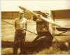
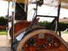
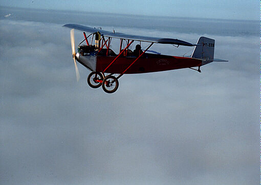
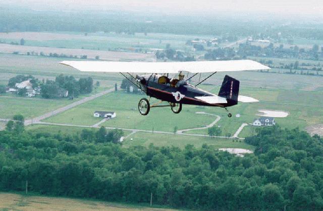
The final design and drawings for the Air camper were completed in 1934. No
further changes have been made to the original drawings. The picture shown
is the last one Bernard built and is flying today.
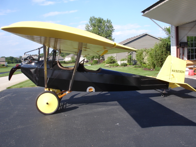
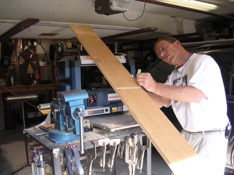
I'm building mine from the 1934 plans. This will definitely
be a LONG TERM project. Take a look at some
of the construction pictures. (double click on picture to enlarge)
 |
 |
 |
 |
| Bernard Pietenpol |
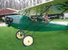
Jack Phillip's Piet |
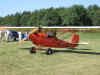
Vitalis Kapler |
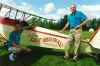
Tom Brown's Piet |
 |
 |
 |
 |
| Dan Helsper's Piet |
Helsper Panel |
Don Emch's Piet |
Ken Perkin's Ship |
|
|
|
|
|
|
|
|
 |
 |
 |
 |
| Andy & Don Pietenpol |
Edison's Piet |
Mike Cuy's Piet |
Frank Pavliga's Piet |
|
|
|
|
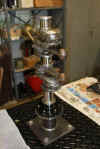
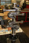
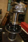
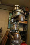
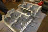
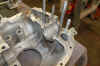
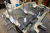
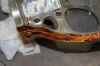
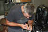
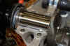
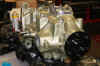
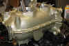
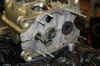
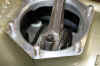
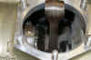
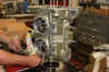
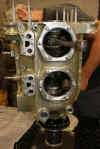
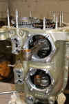
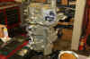
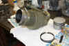
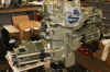
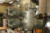
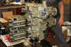
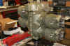
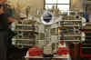
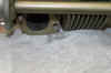
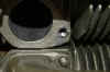
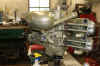
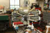
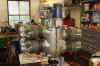
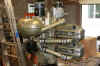
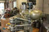
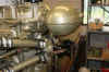
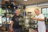
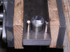
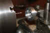
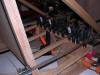
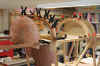
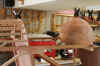
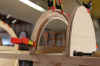
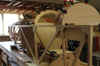
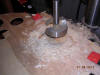
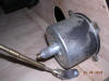
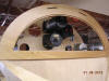
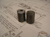
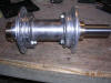
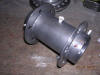
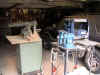
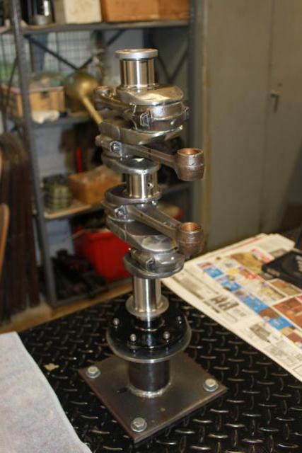
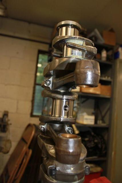
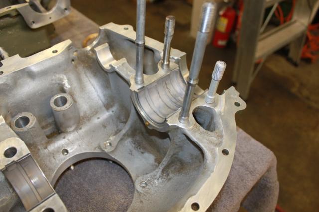
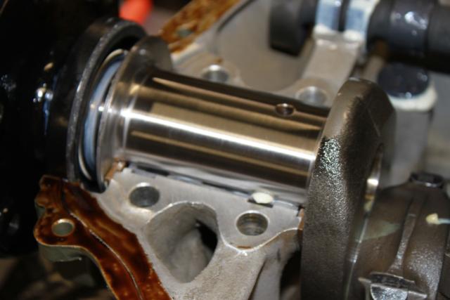
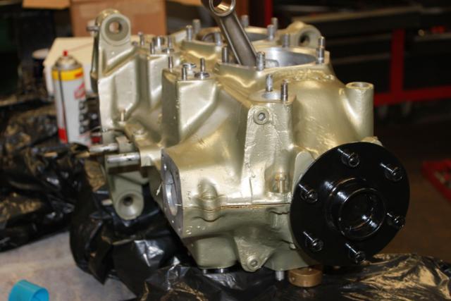
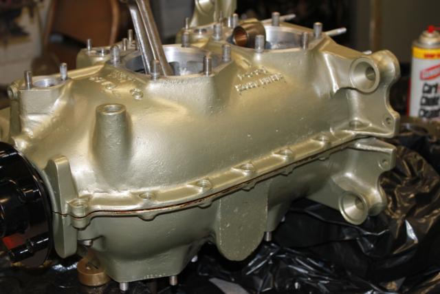
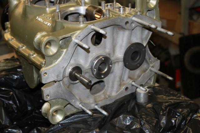
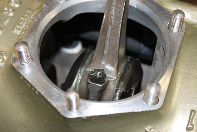
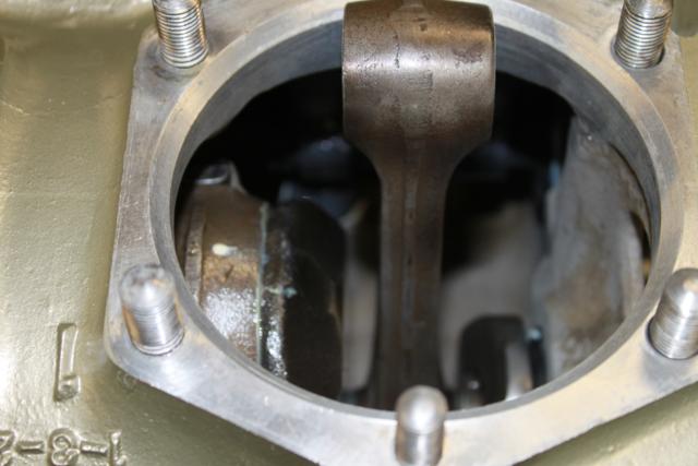
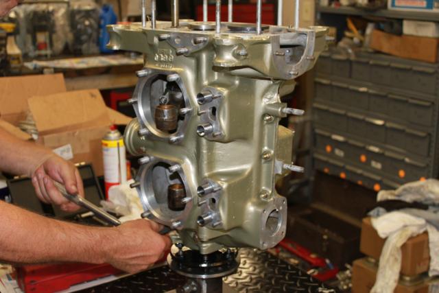
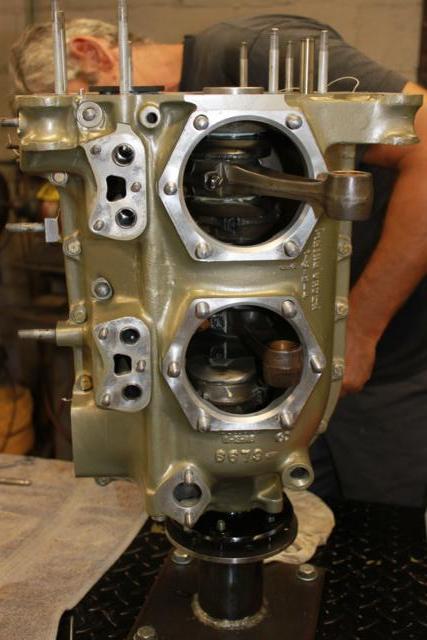
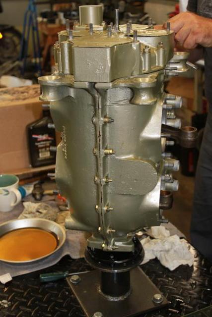
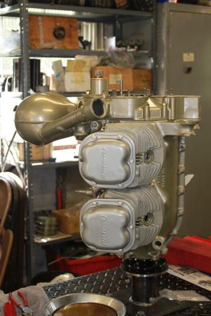
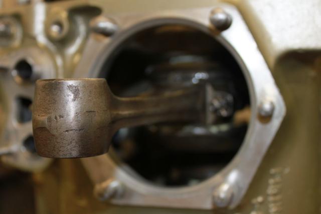
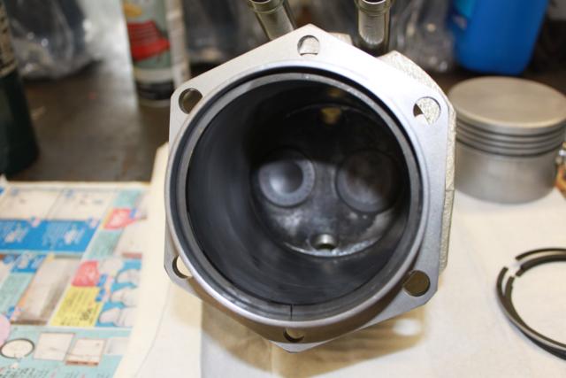
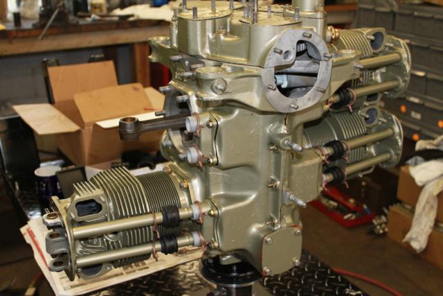
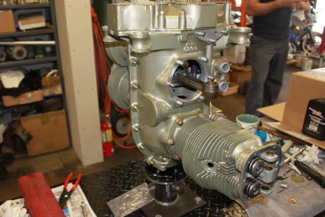
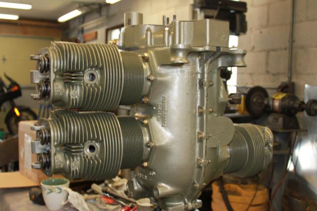
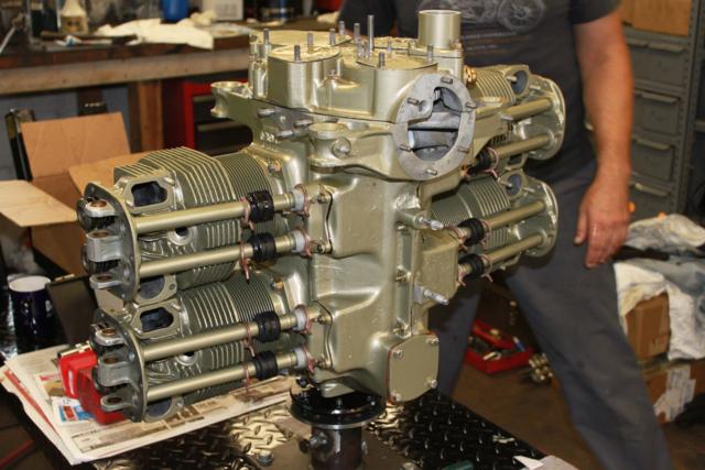
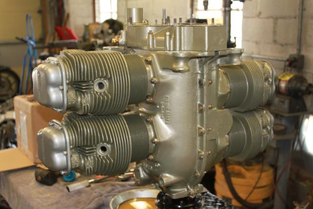
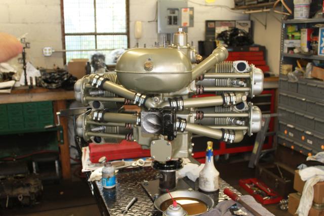
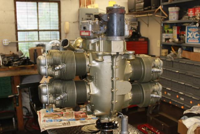
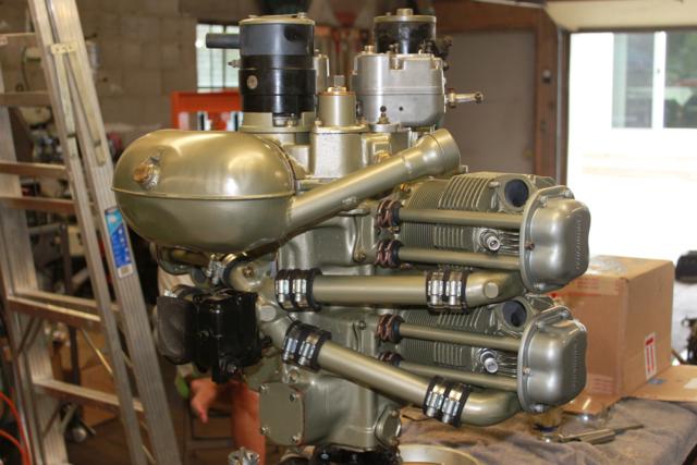
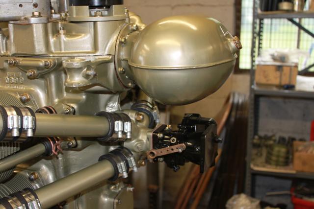
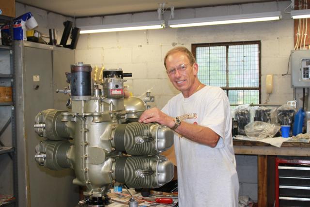
| CONSTRUCTION PHOTOS
(Engine Assembly) |
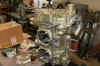
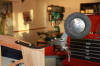
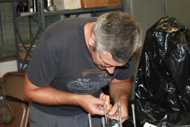
| Tom Wottrung did the pre-assembly, a
fantastic fellow! |
 |
 |
 |
 |
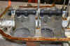
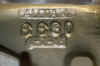
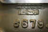
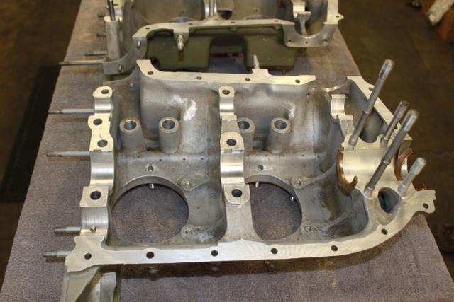
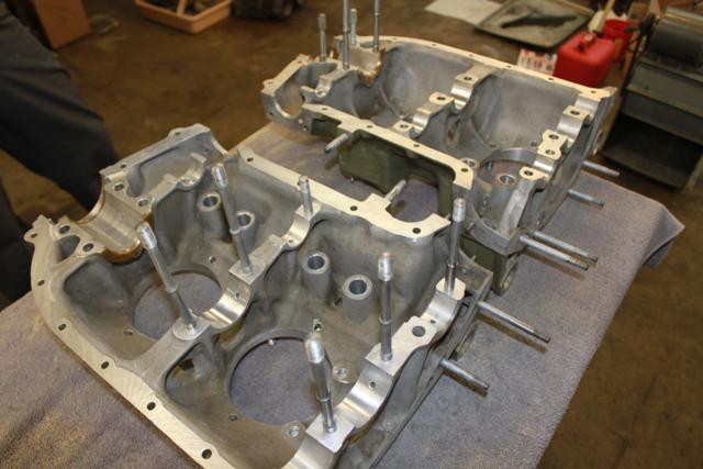
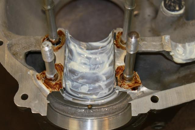
| Starting assembly |
|
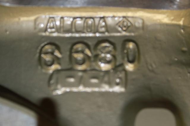
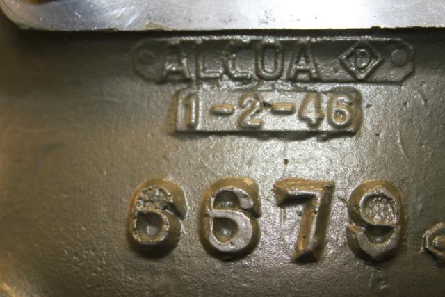
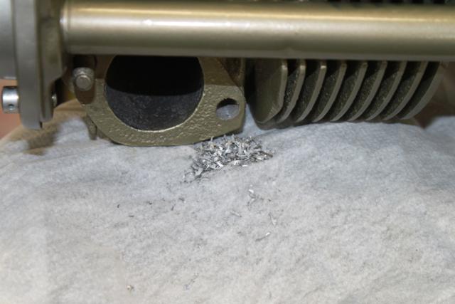
Original tolerances |
|
 |
 |
 |
 |
 |
 |
 |
 |
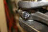
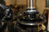
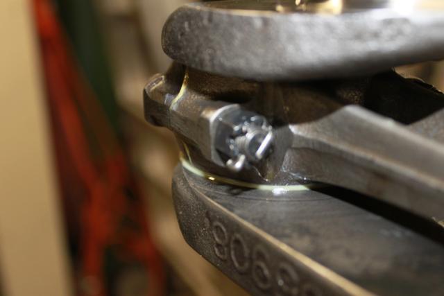
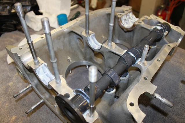
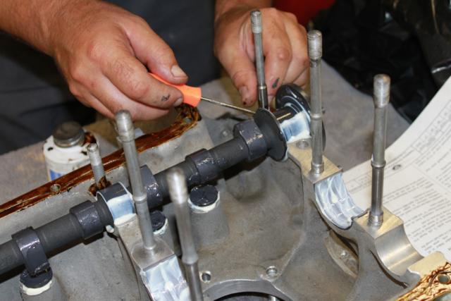
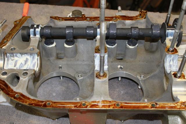
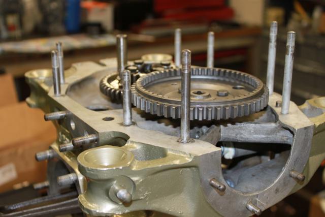
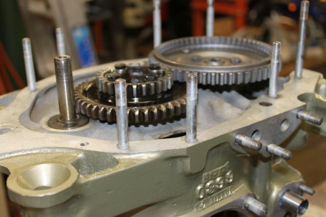
| re-manned cam |
Silk thread |
|
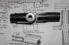
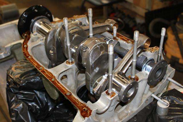
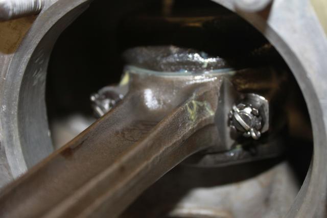
Main bearing |
 |
 |
 |
 |
| Tom |
|
|
|
|
|
 |
 |
 |
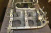
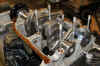
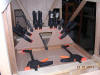
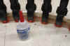
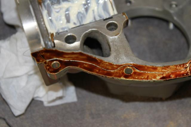
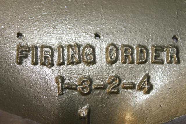
| That's an aircraft engine, no snapping
crank here! Case closed |
 |
 |
 |
 |
 |
 |
 |
 |
 |
 |
 |
 |
 |
 |
 |
 |
 |
 |
 |
 |
 |
 |
 |
 |
 |
 |
 |
 |
 |
 |
 |
 |
 |
 |
 |
 |
|
|
Proud owner |
Fantastic Teacher! |
|
|
|
|
|
|
|
|
|
|
|
|
|
|
|
|
|
|
|
|
|
|
|
|
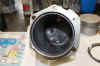
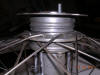
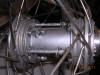
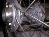
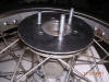
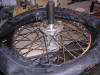
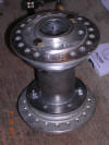
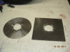
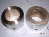
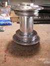
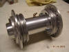
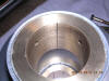
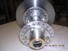
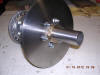
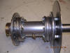
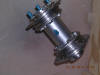
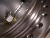
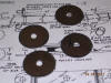
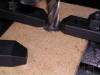
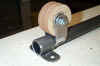
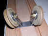
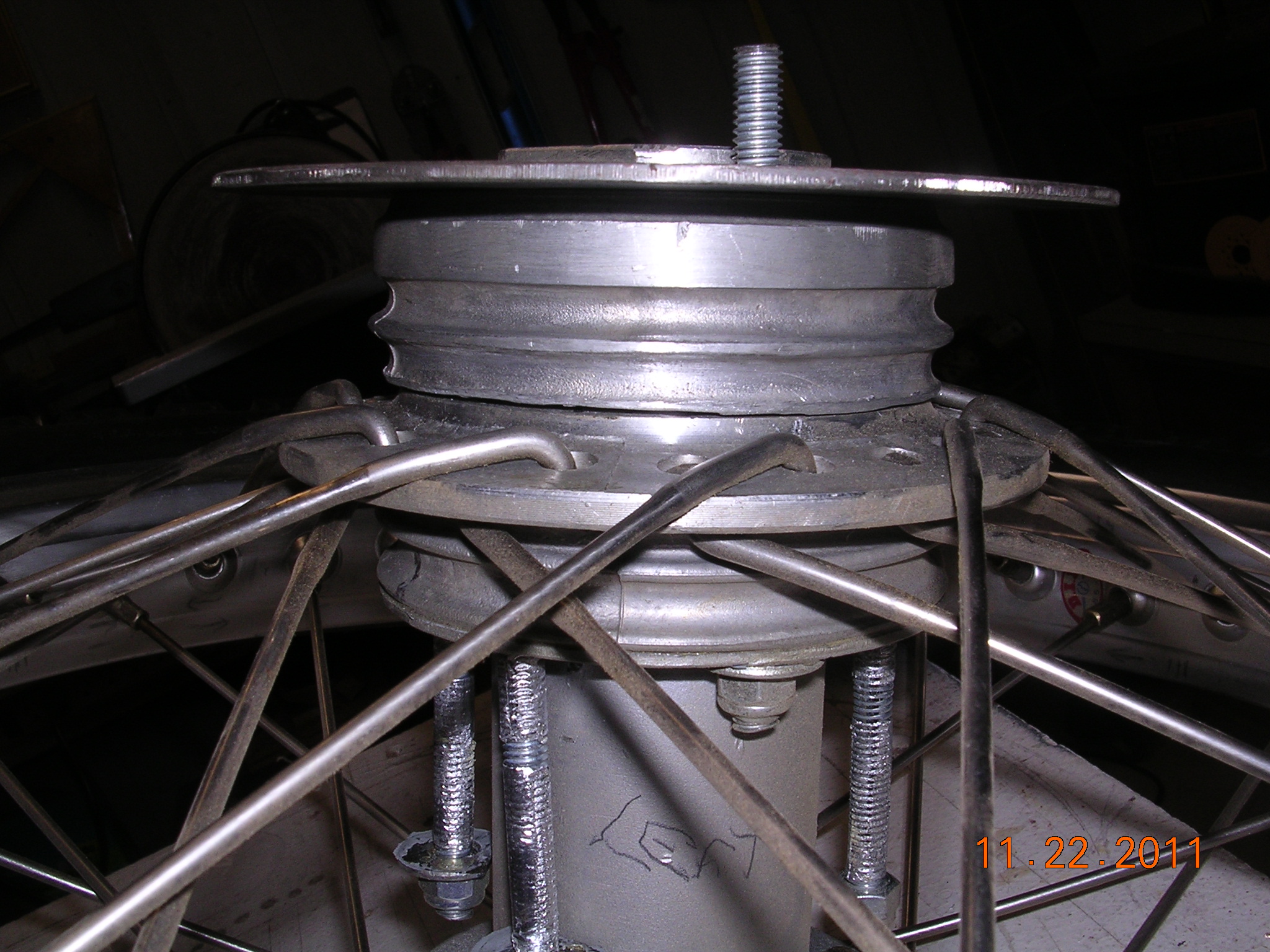
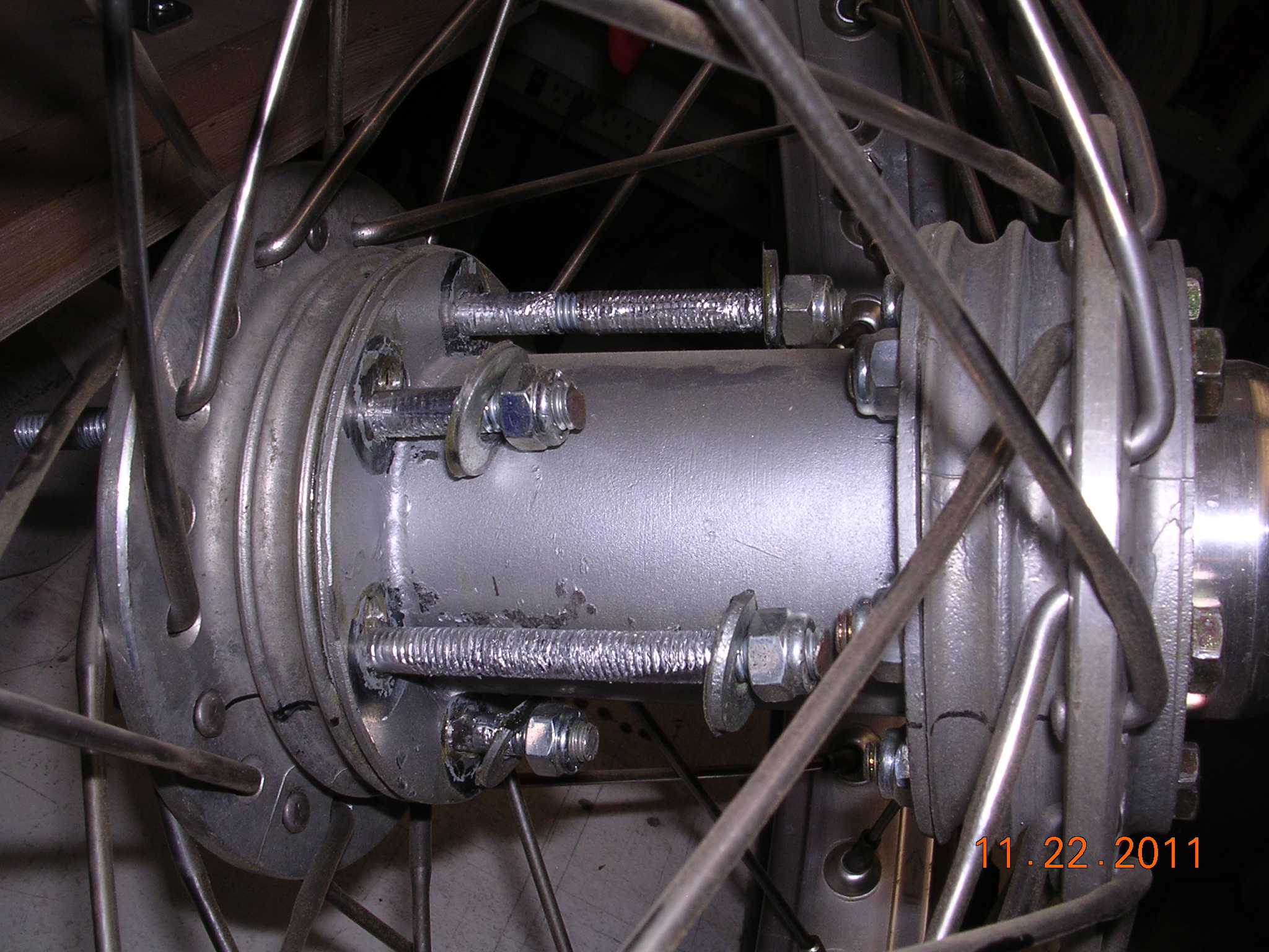
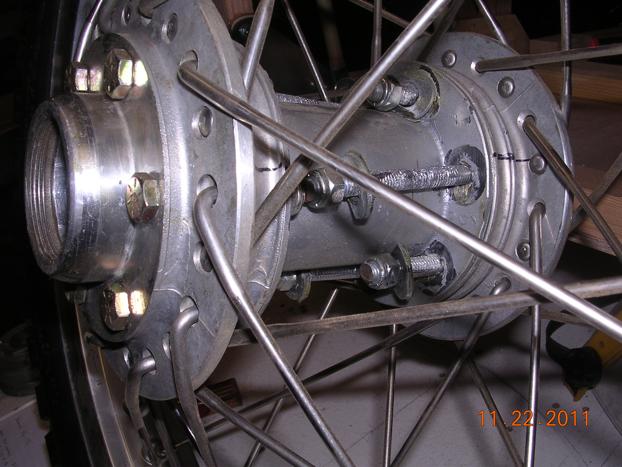
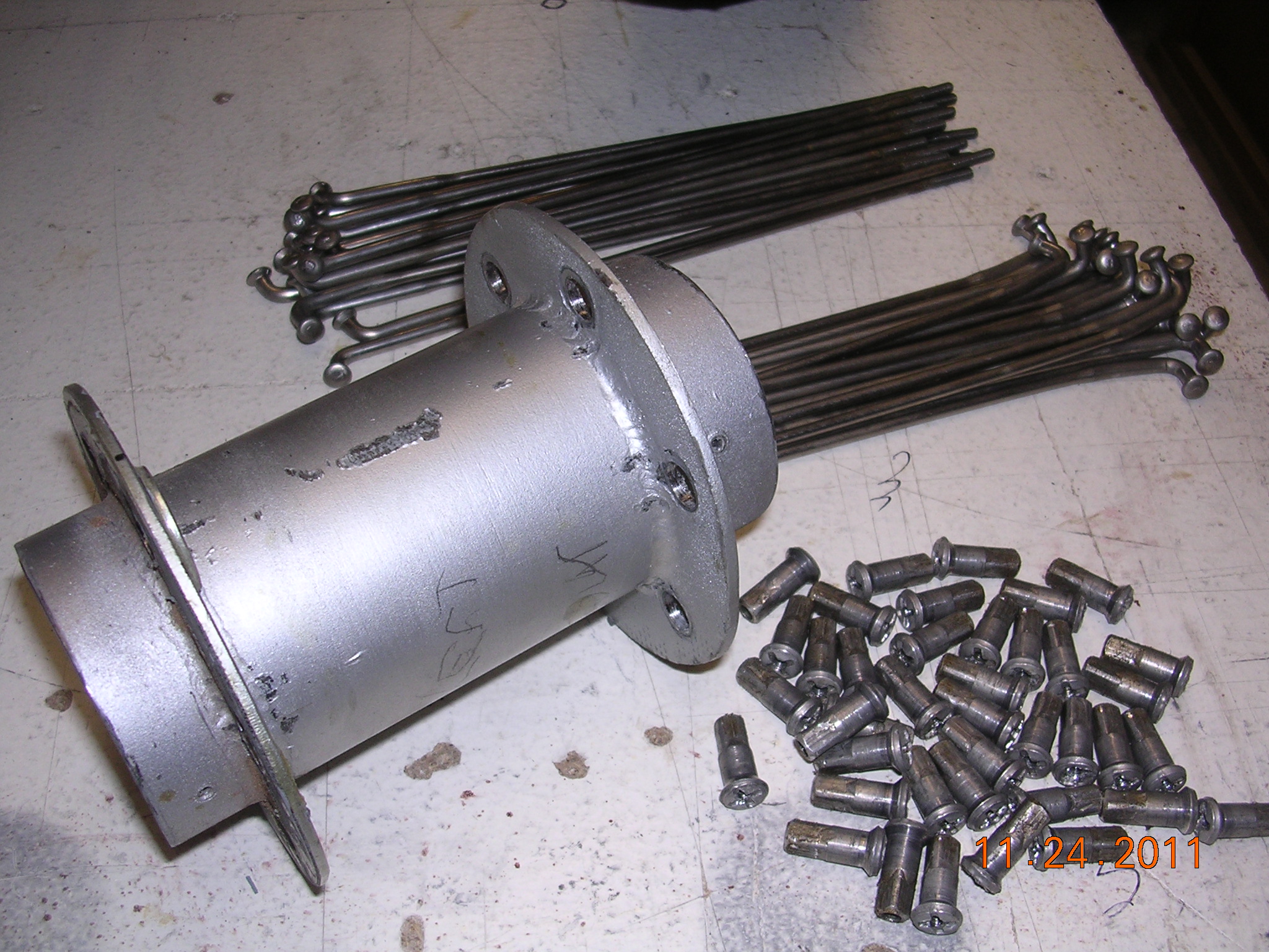
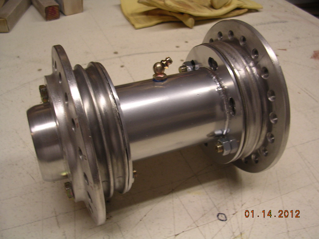
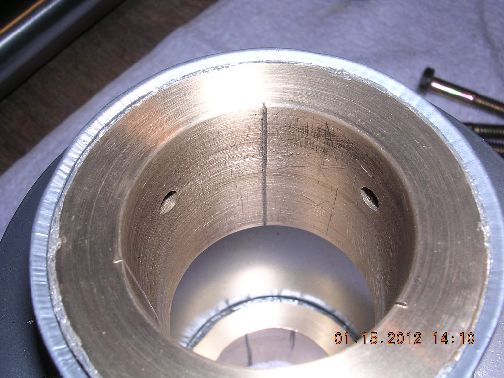
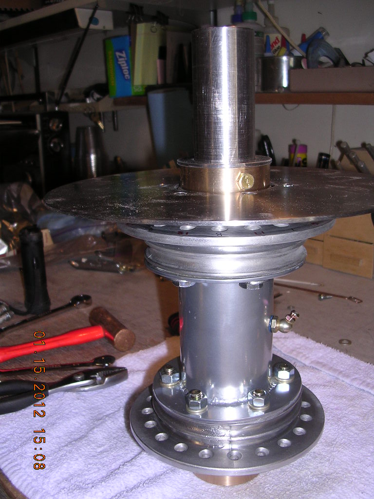
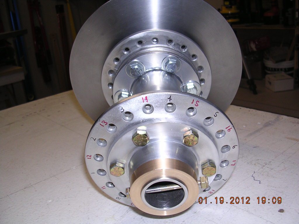
| CONSTRUCTION PHOTOS
(Wheels) |
 |
 |
 |
 |
 |
 |
 |
 |
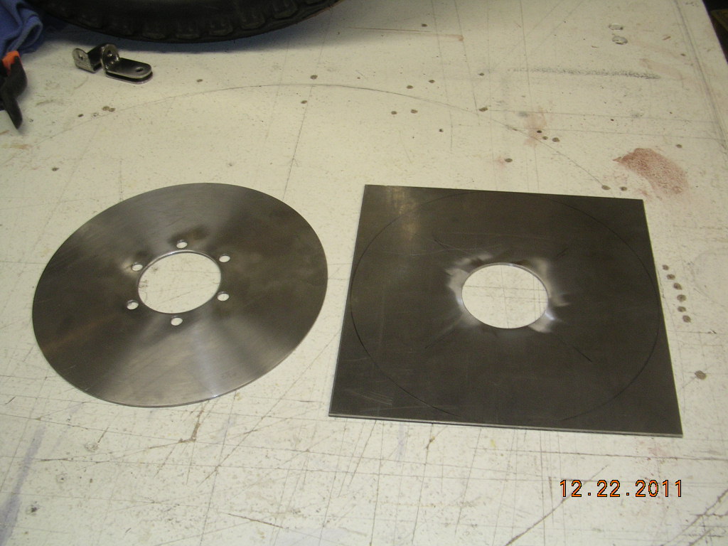
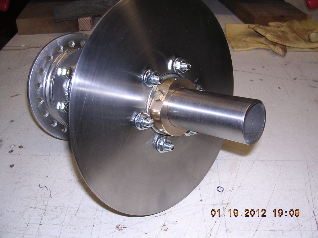
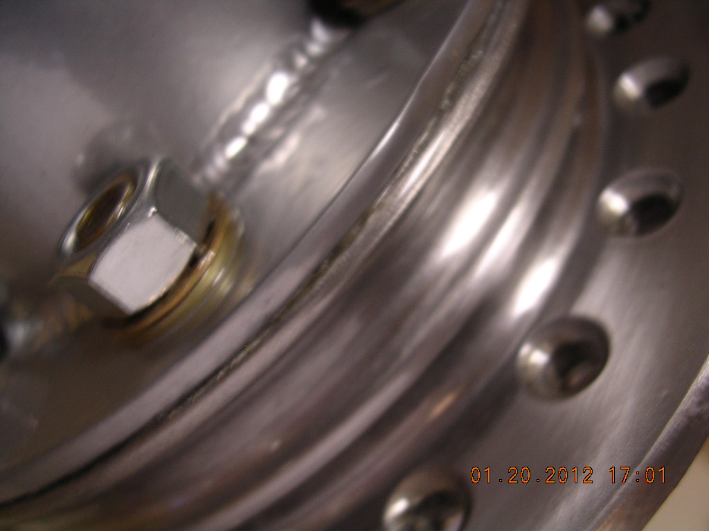
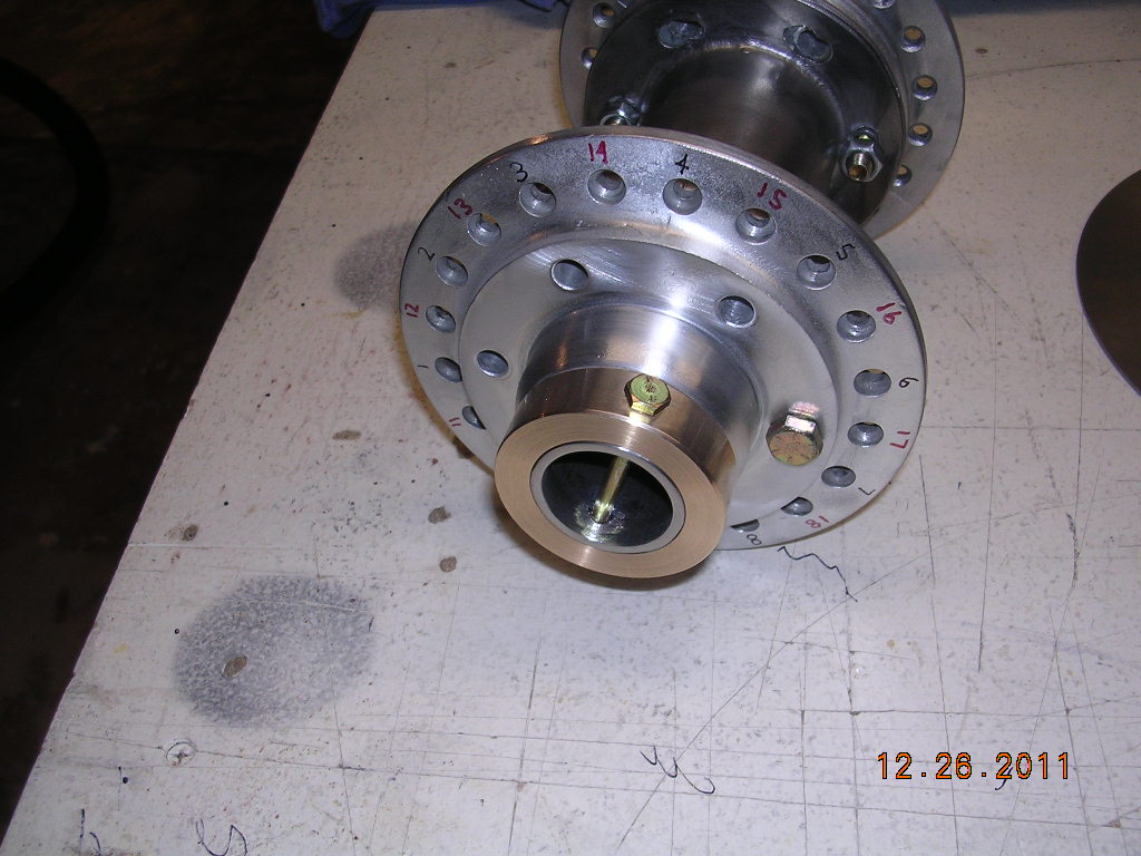
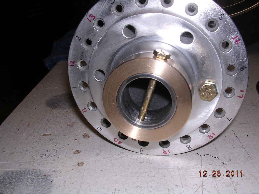
| This is what I started with, a mess, brake
disk too small, uneven hub |
Very poor work |
 |
 |
 |
 |
|
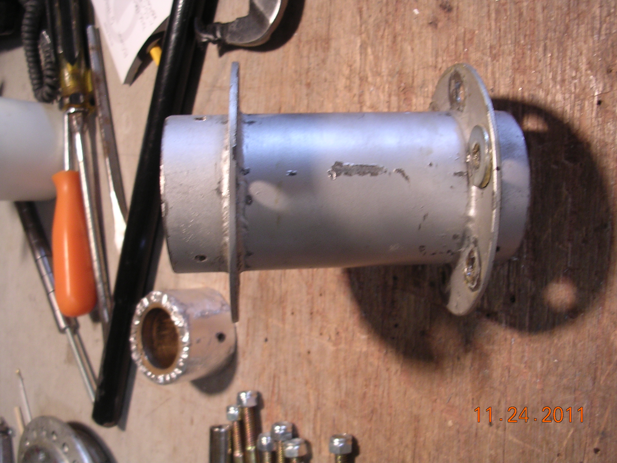
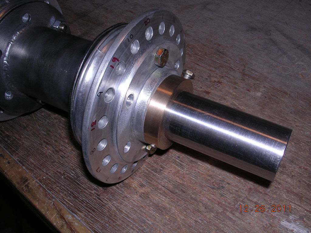
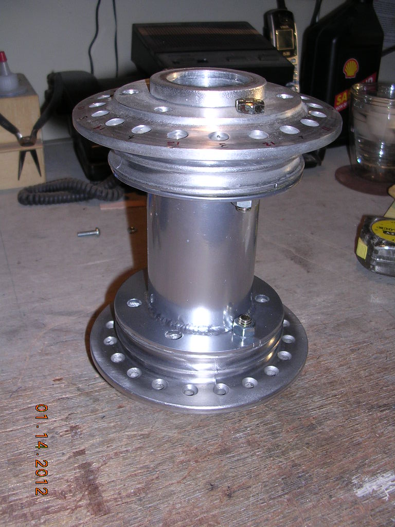
9" disk |
Cleaned up the left |
Coming together |
 |
 |
 |
 |
|
|
|
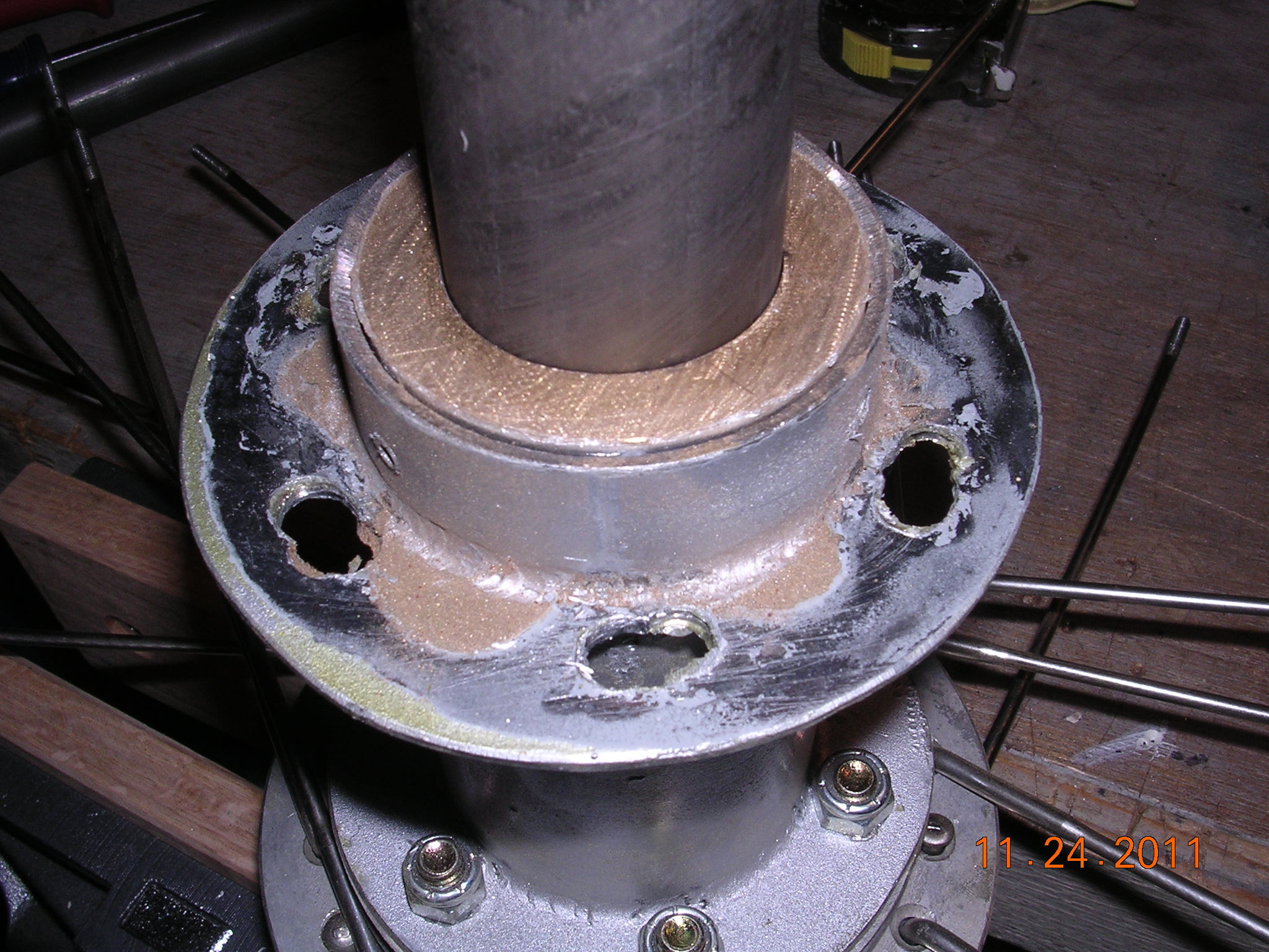
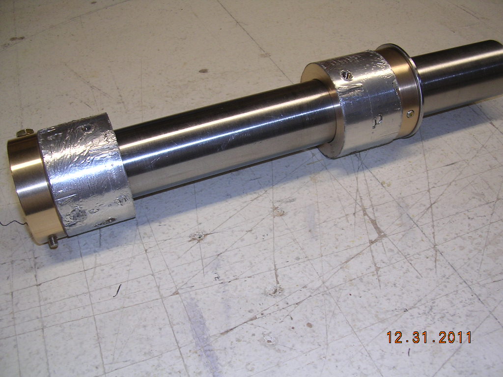
groove for grease |
|
|
|
|
|
|
|
|
 |
 |
 |
 |
|
|
|
|
 |
 |
 |
|
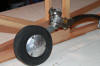
| Silver coat |
Gloss 2nd coat |
Nice gloss |
|
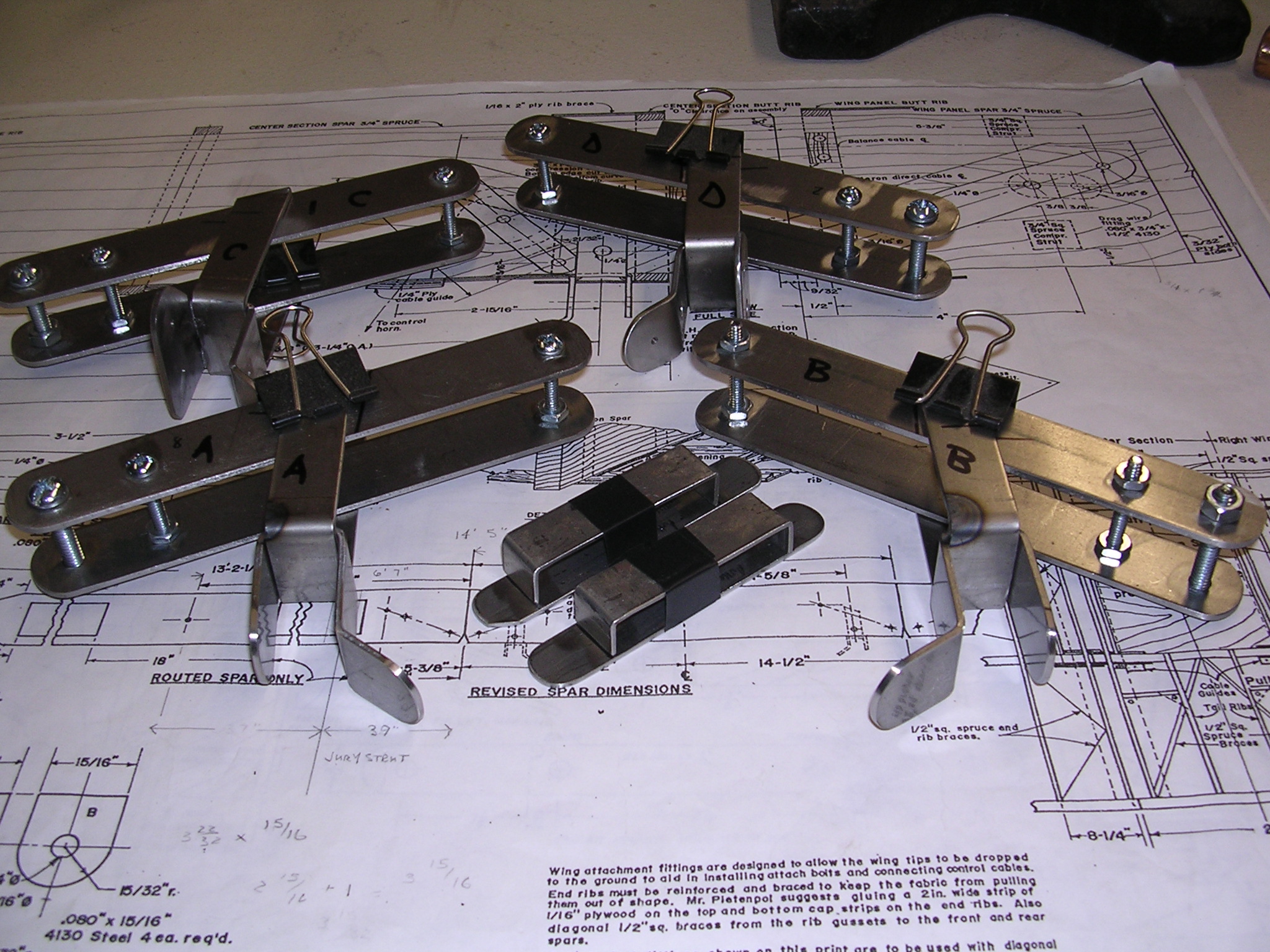
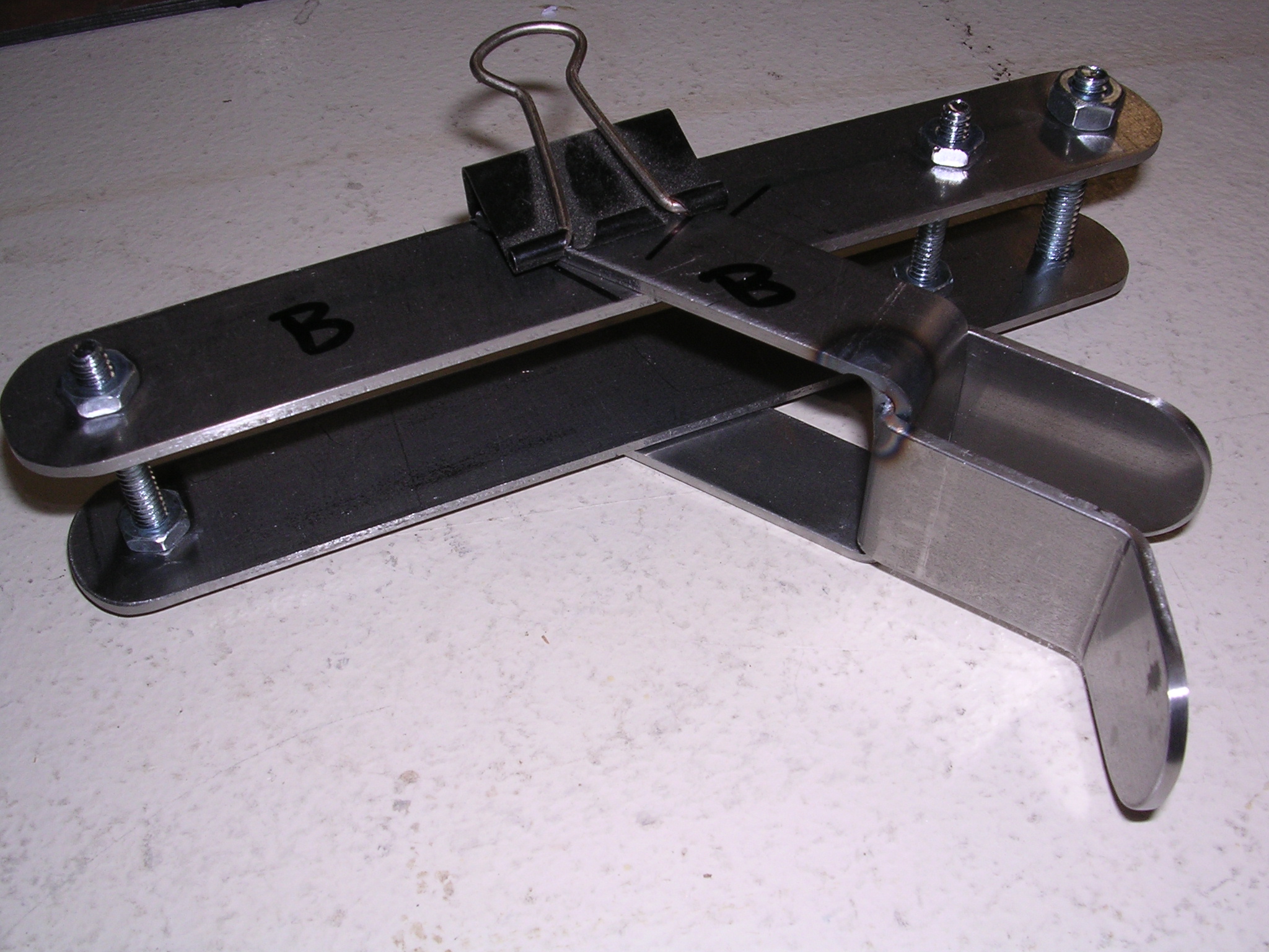
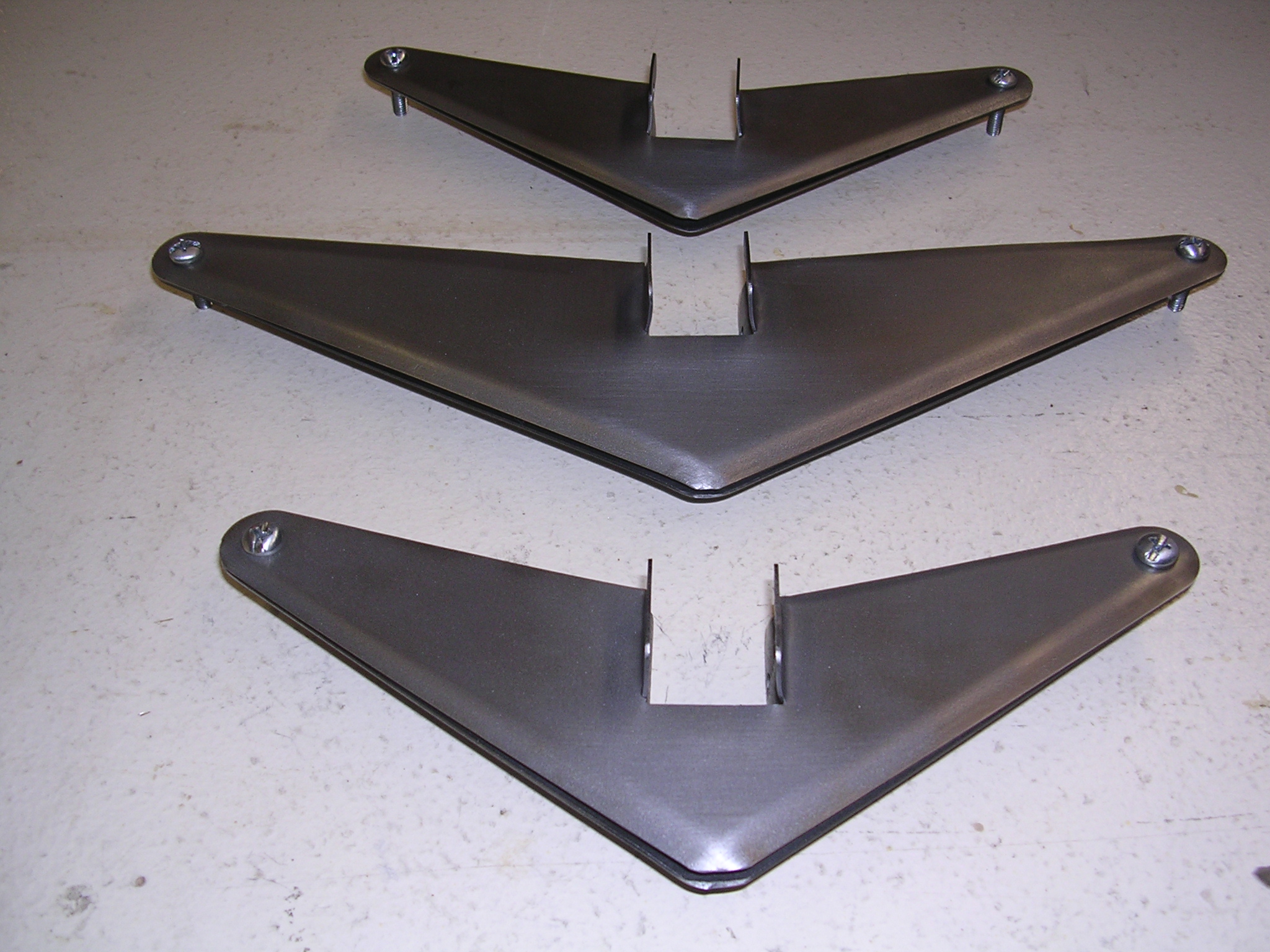
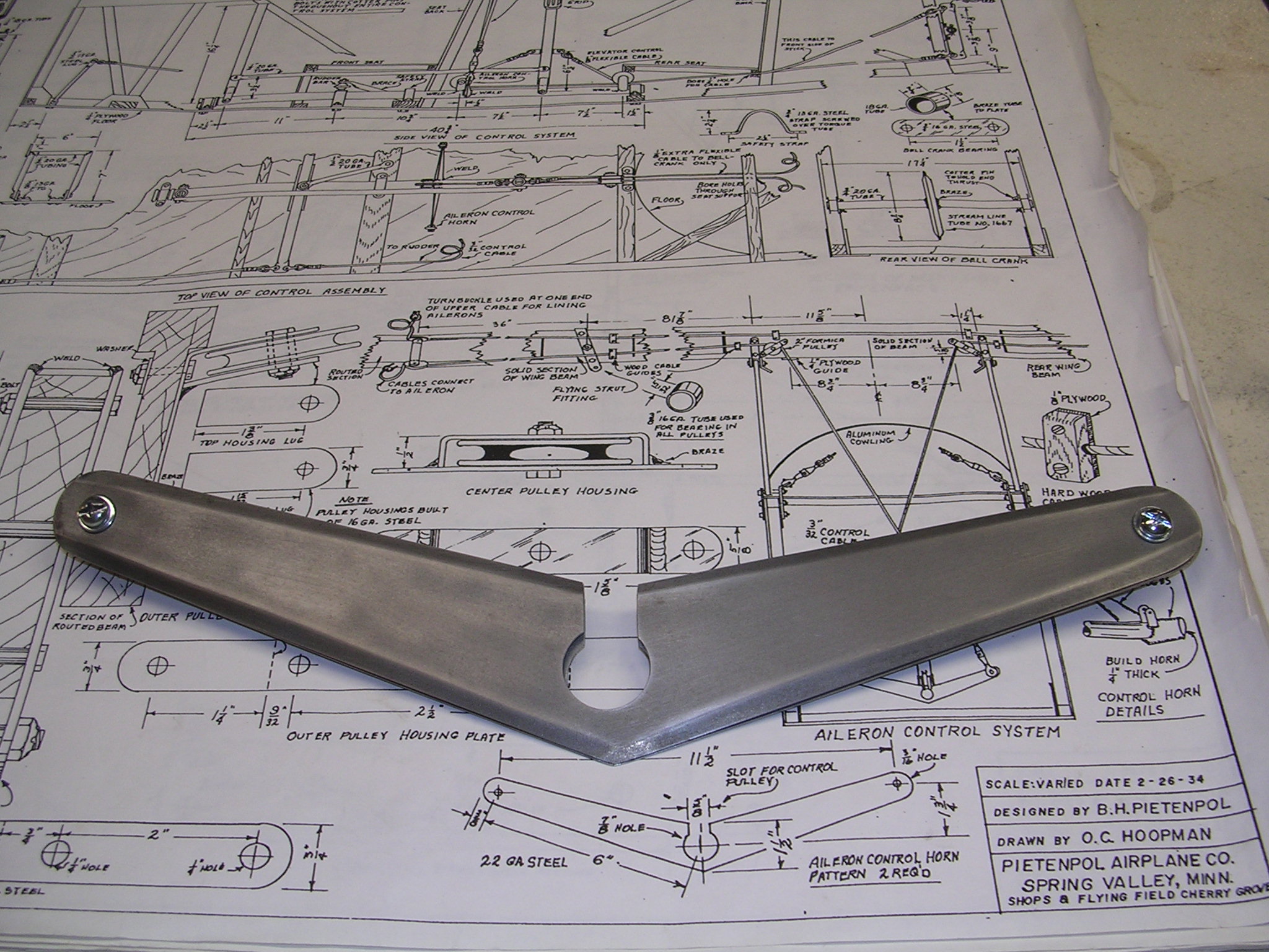
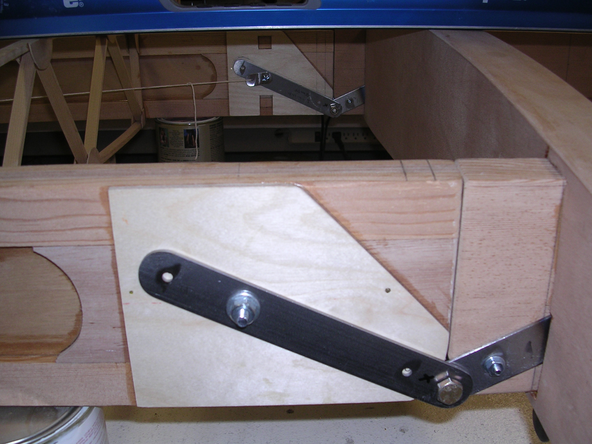
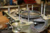
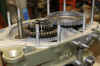
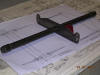
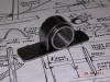
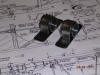
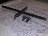
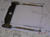
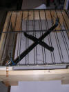
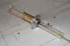
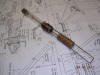
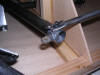
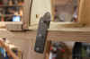
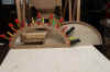
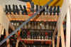
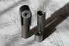
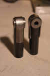
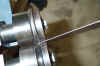
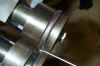
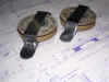
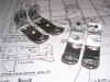
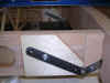
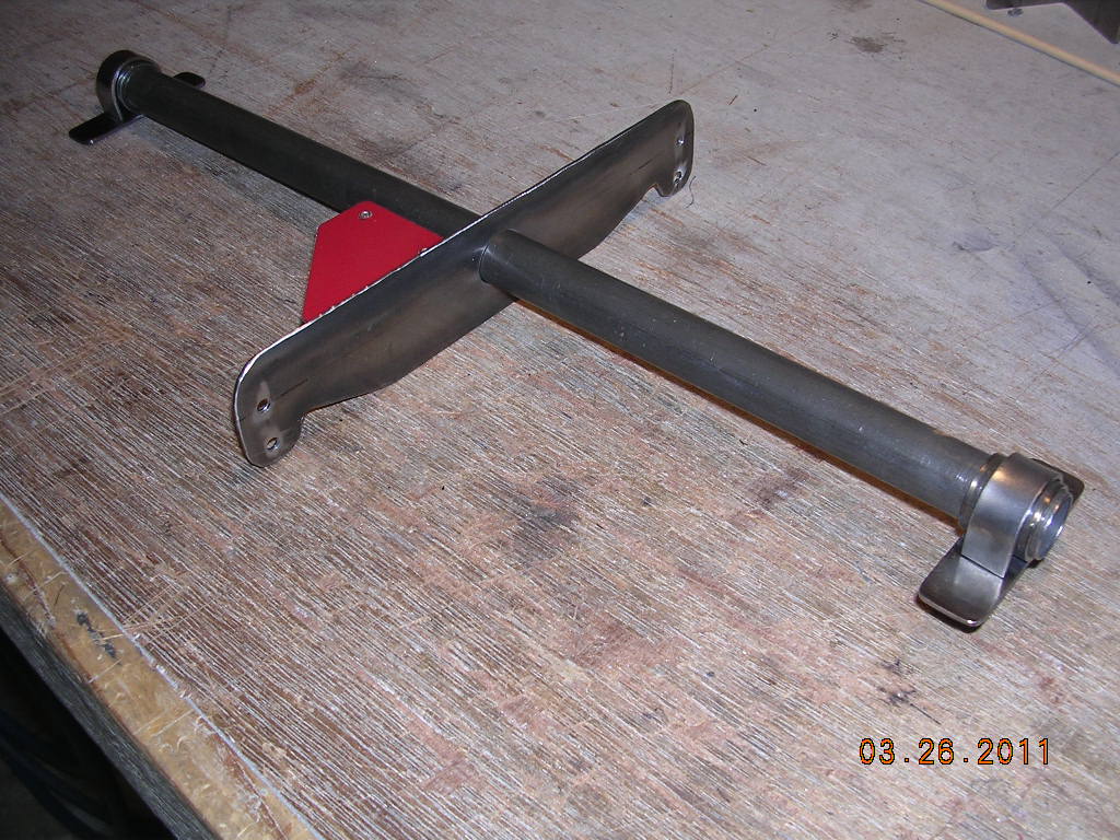
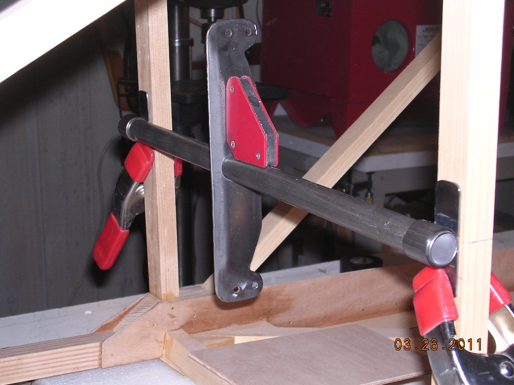
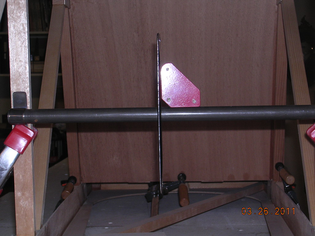
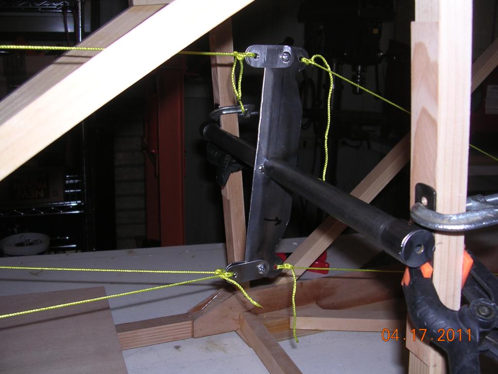
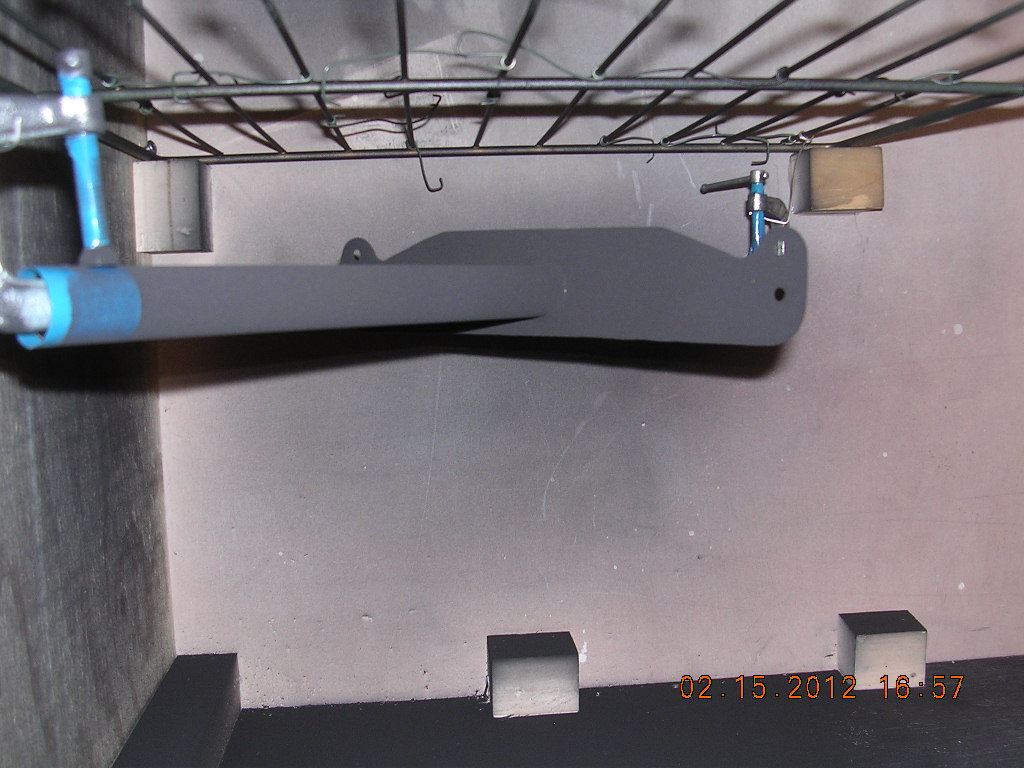
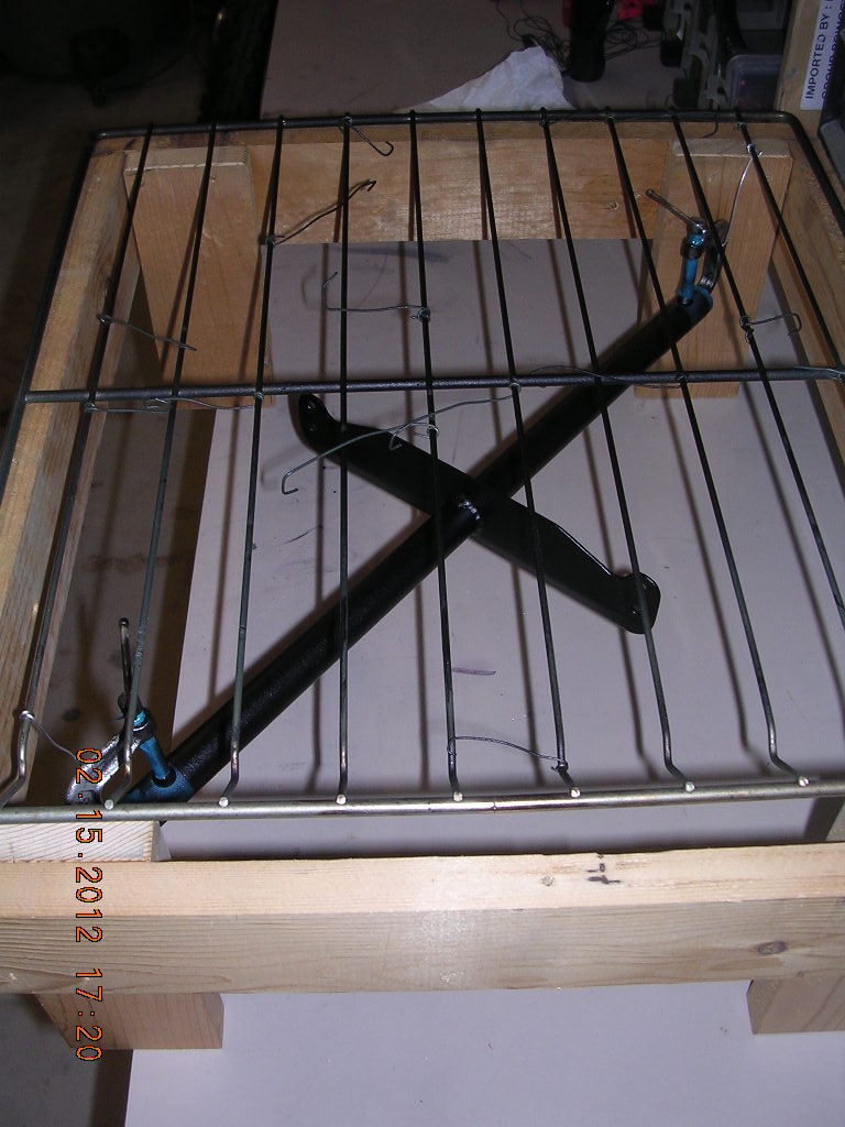
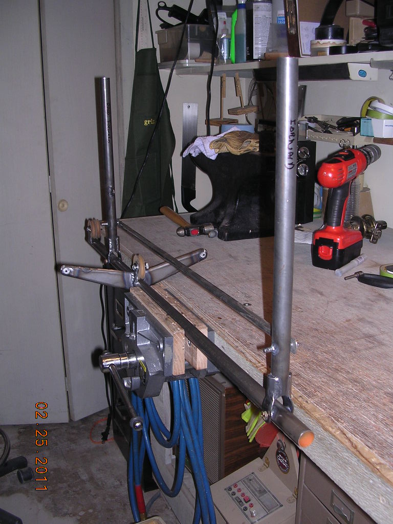
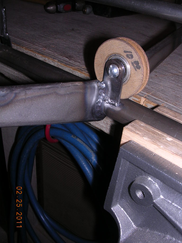
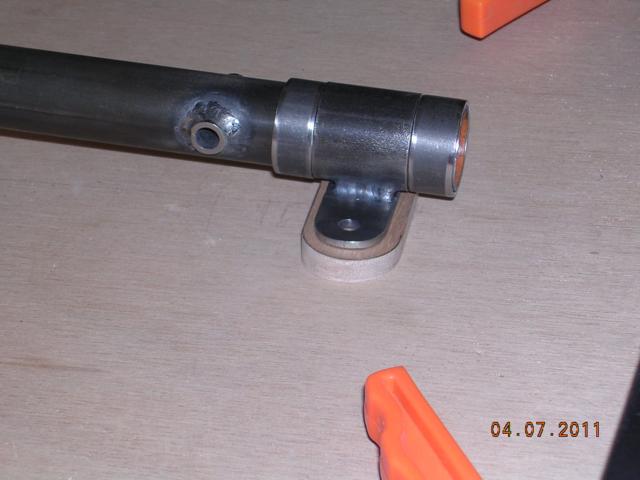
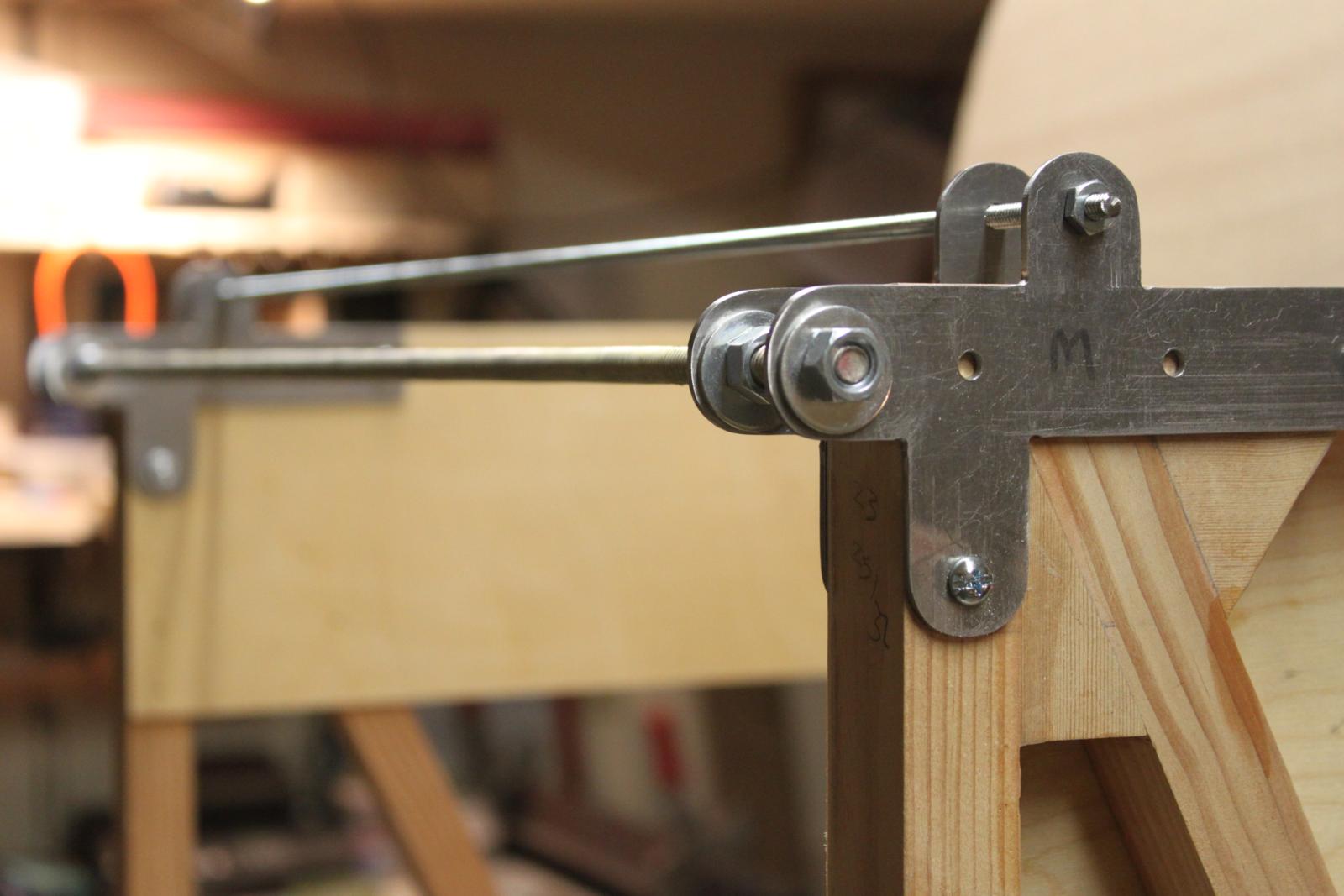
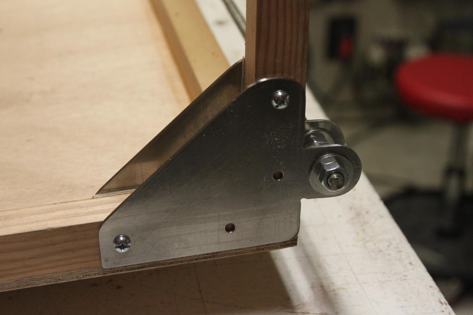
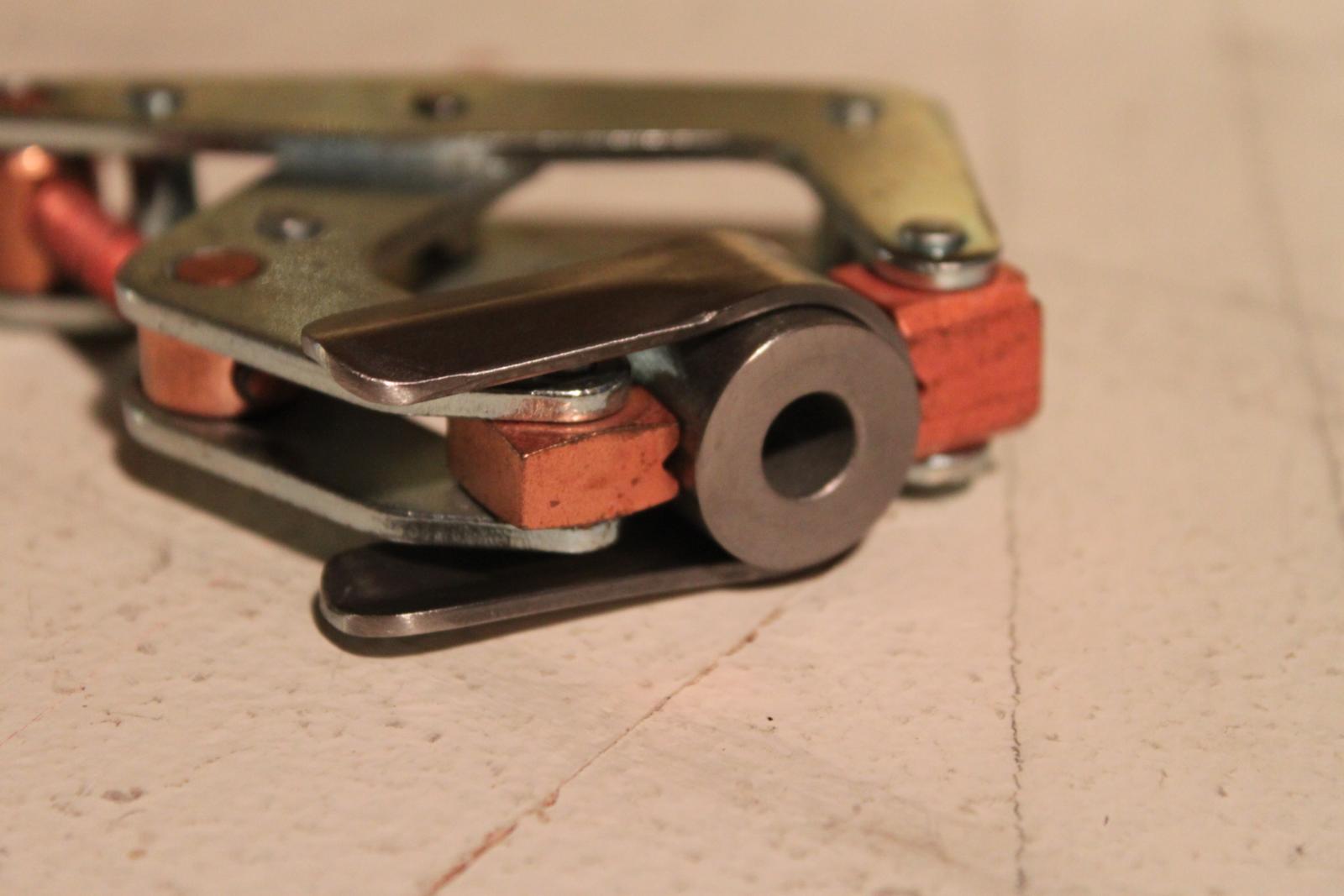
| CONSTRUCTION PHOTOS
(Bell Crank) |
 |
 |
 |
 |
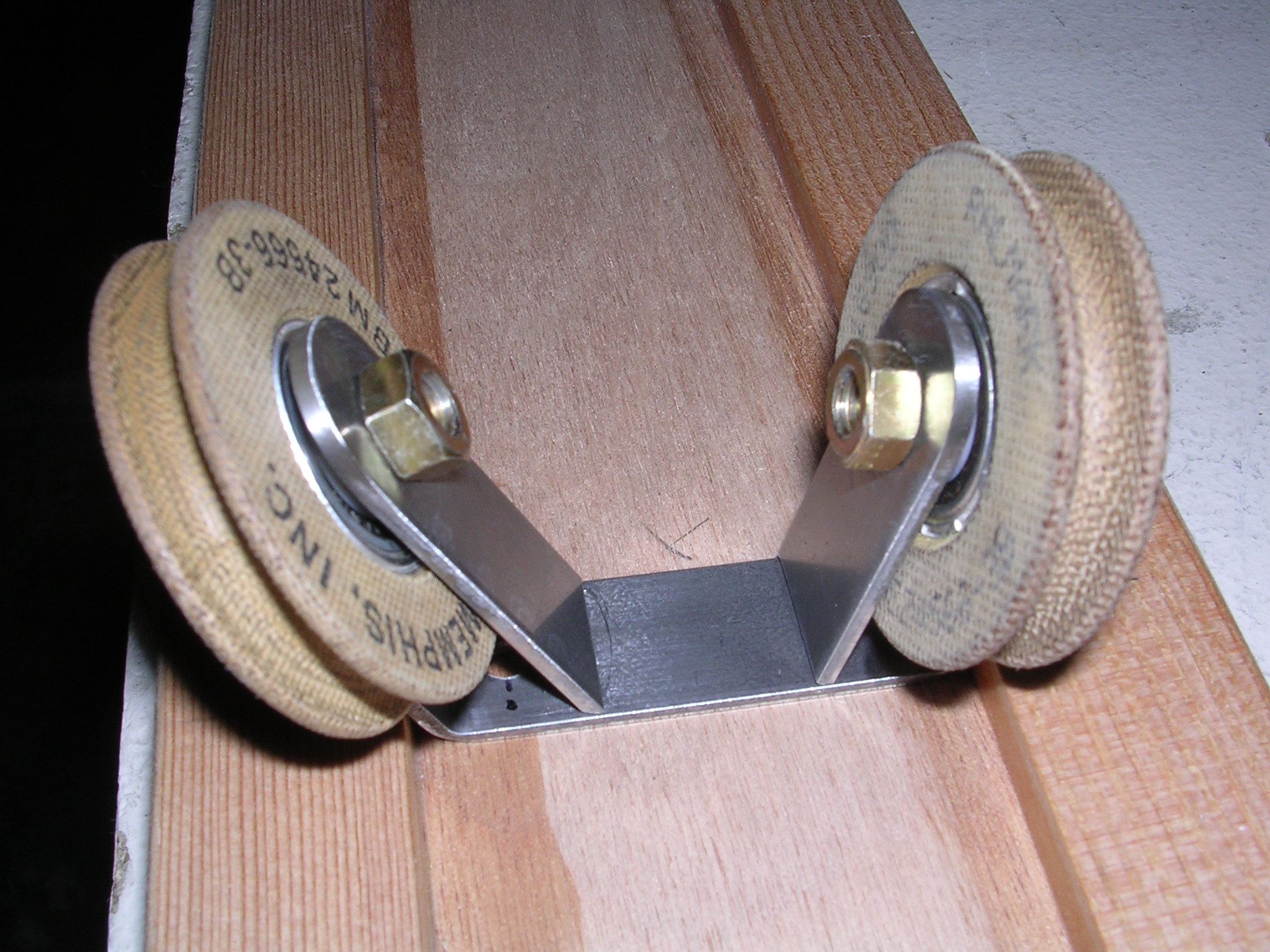
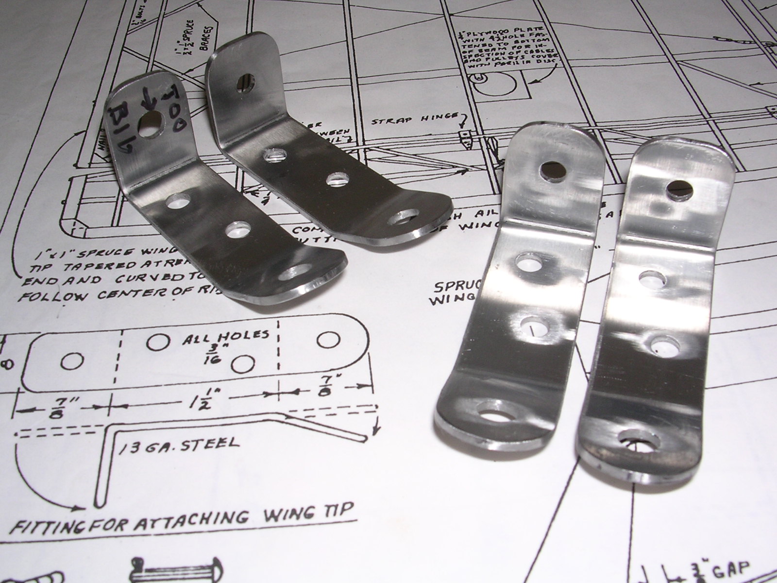
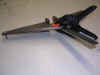
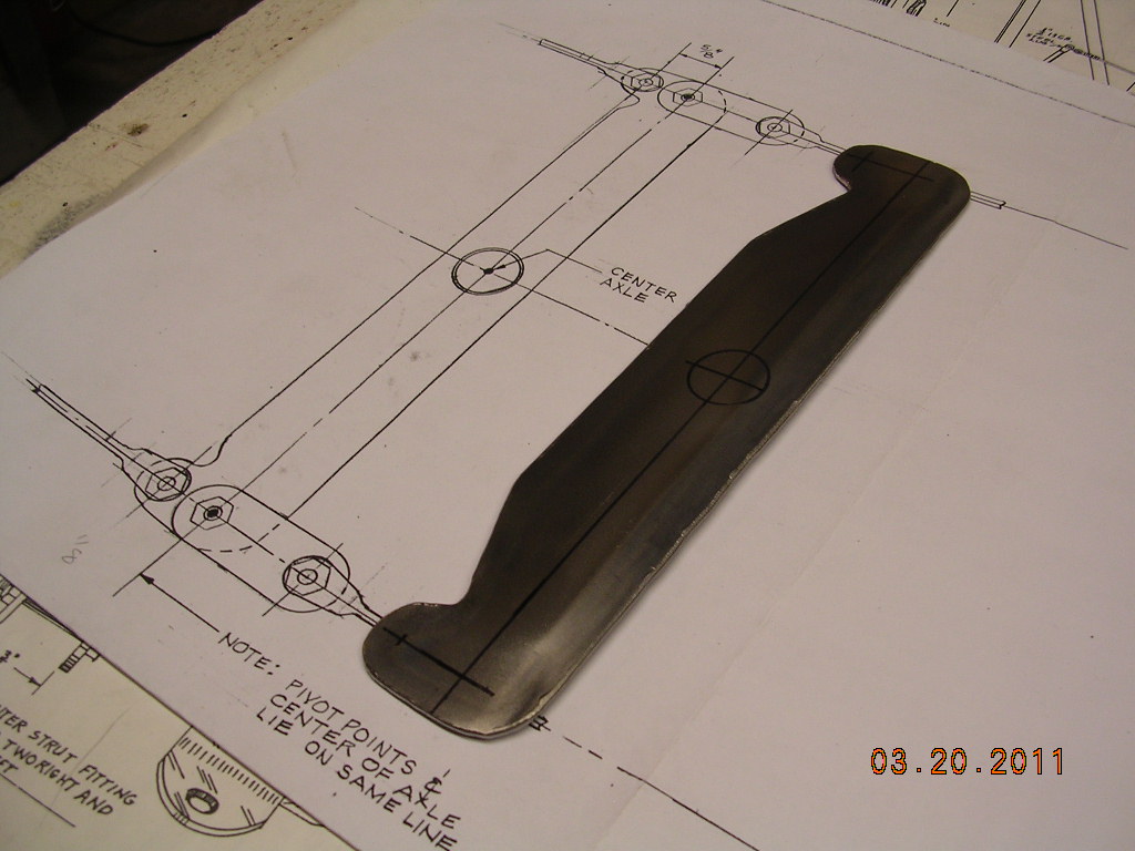
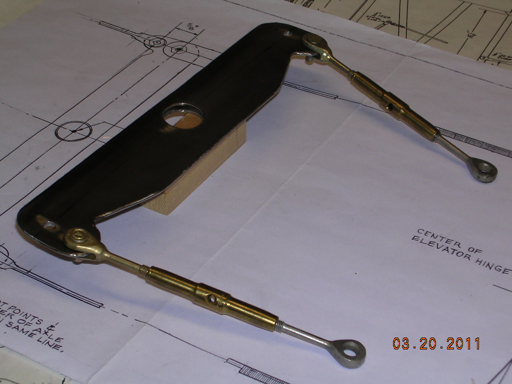
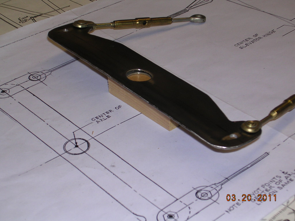
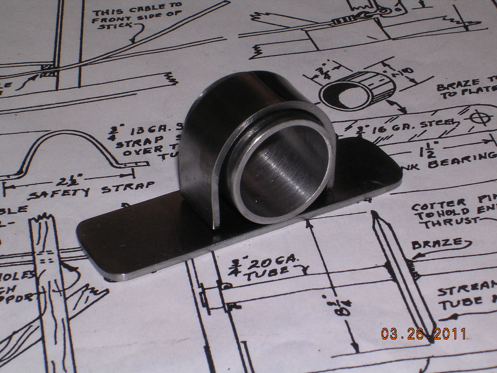
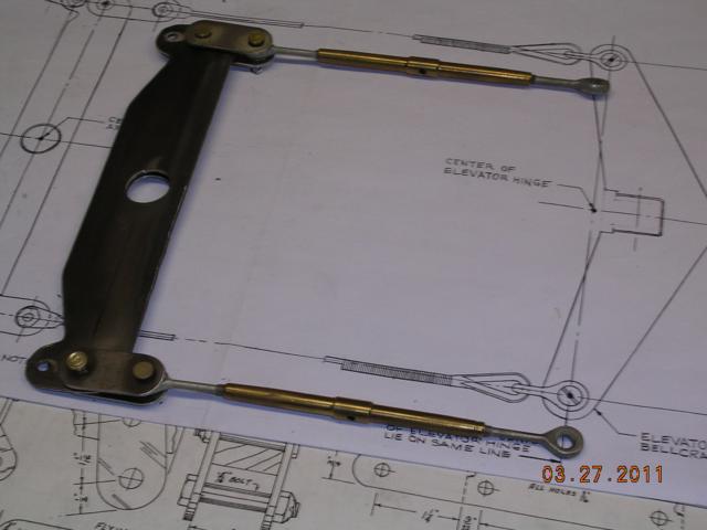
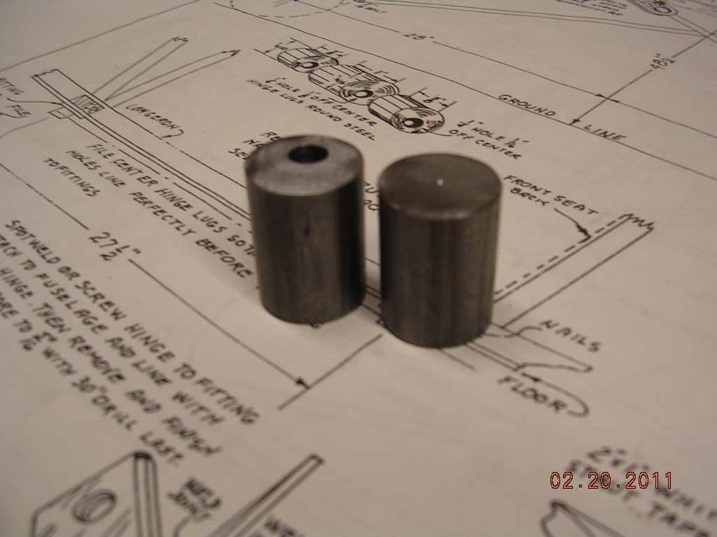
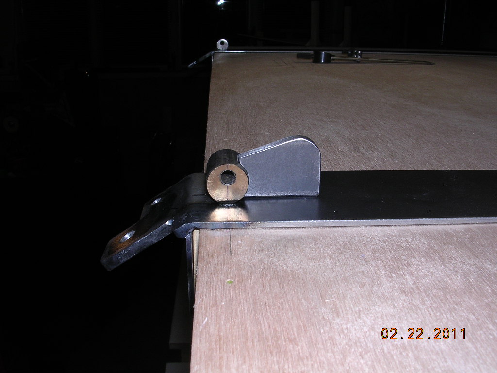
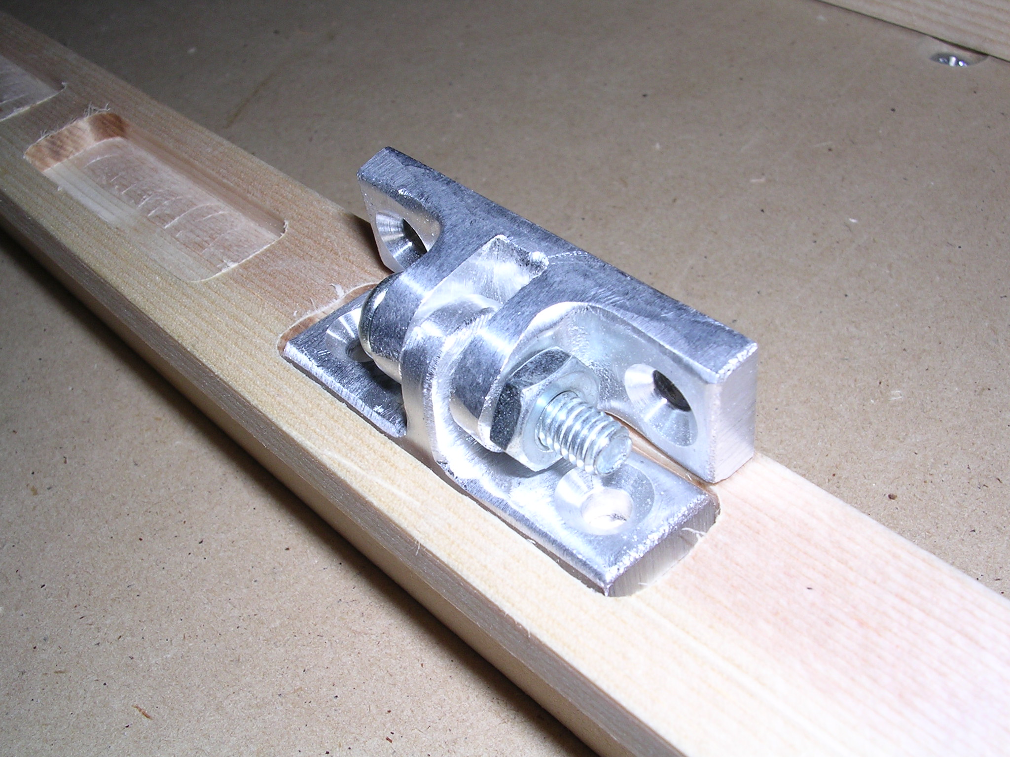
| Ken Perkins design |
Turned bearings to fit |
Design ensures less slack in cables |
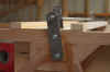
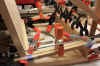
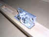
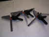
| 2 pictures on right - part is shown
reverse of plans |
 |
 |
 |
 |
 |
 |
 |
 |
 |
 |
 |
 |
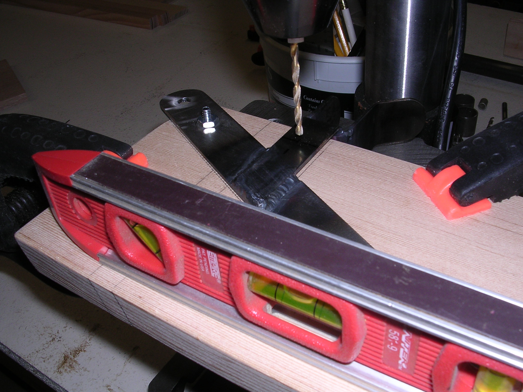
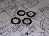
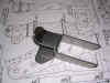
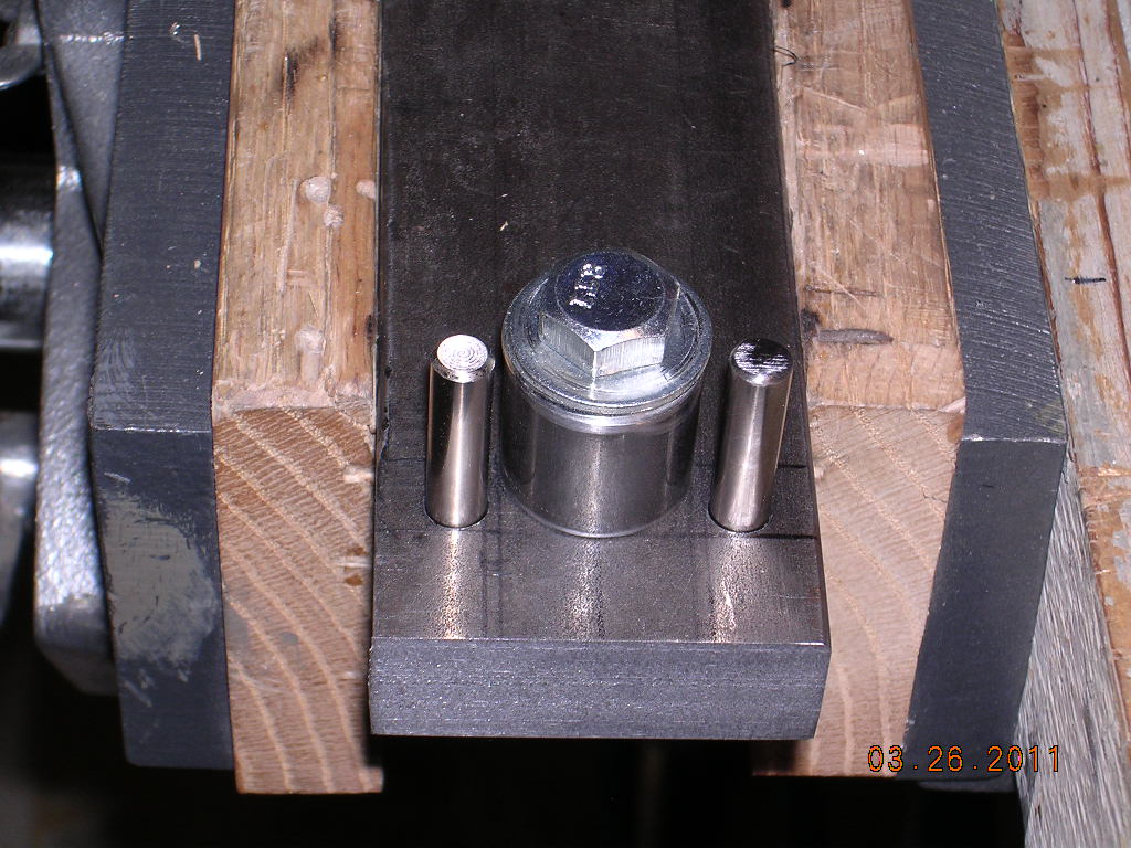
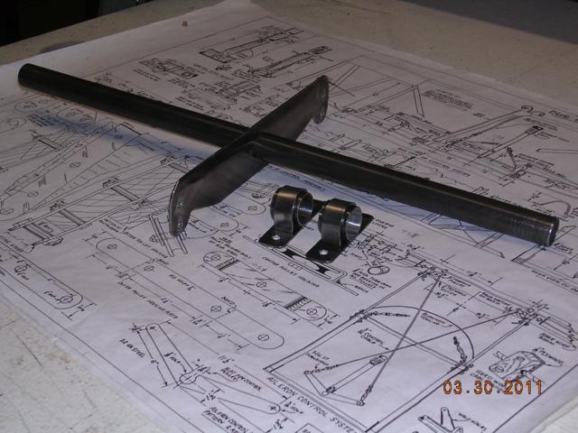
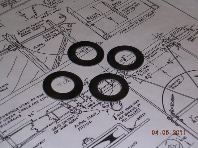
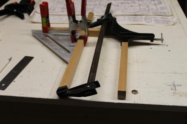
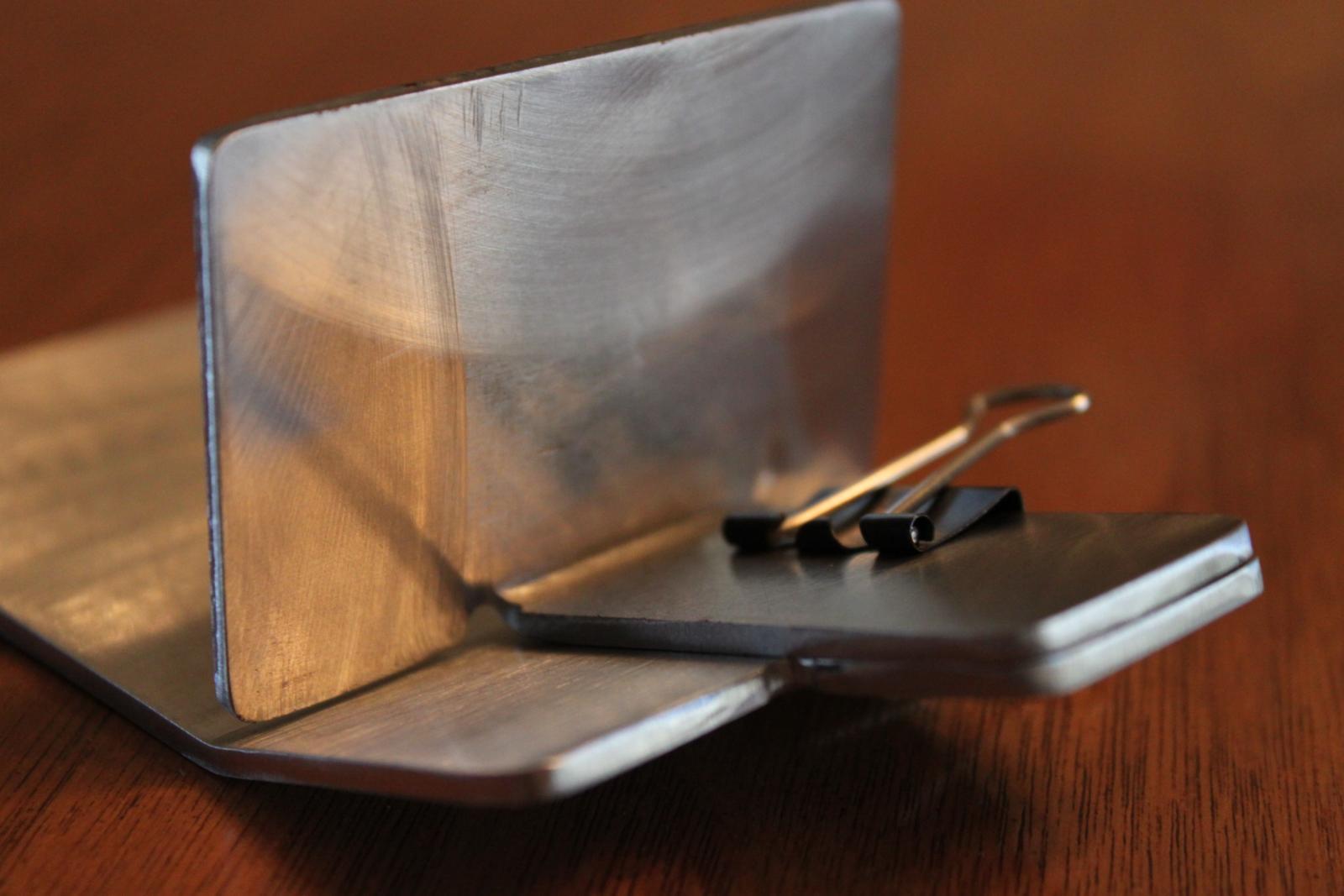
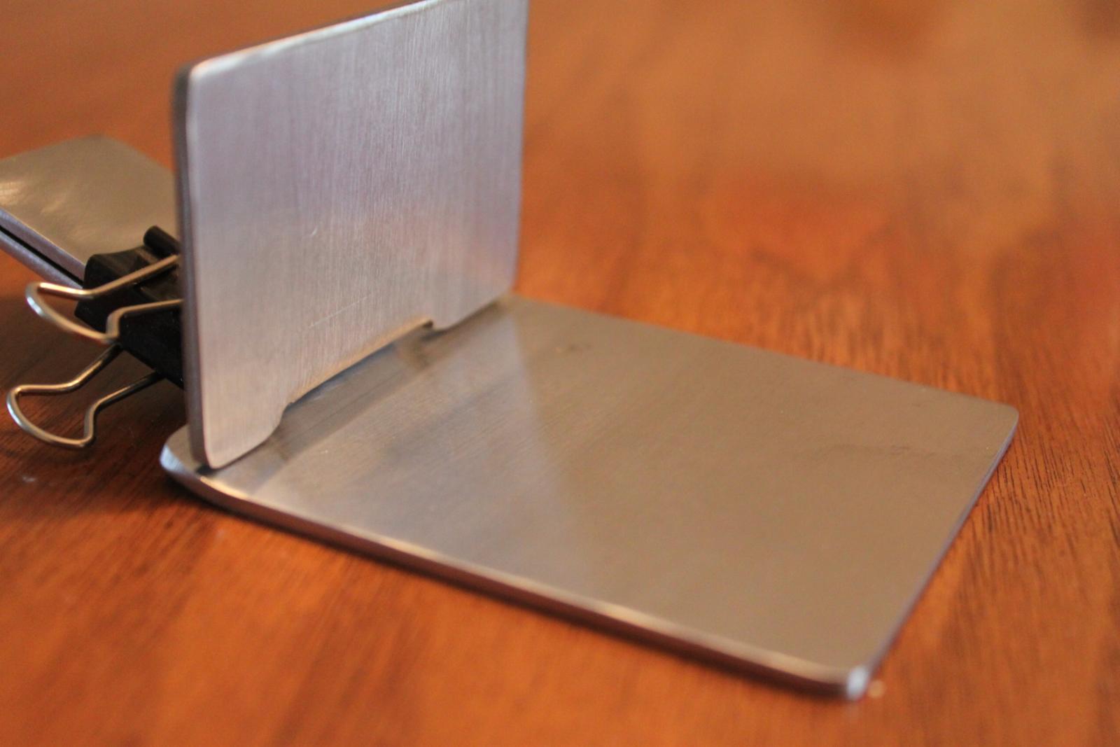
| Machined thrust washers out of .050 for
each end of Bell Crank tube |
 |
 |
 |
 |
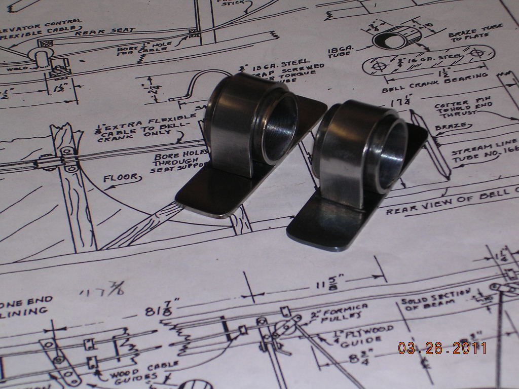
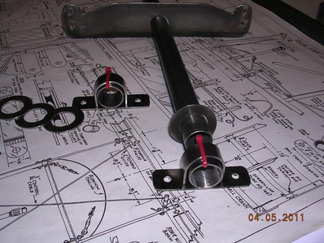
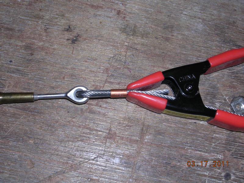
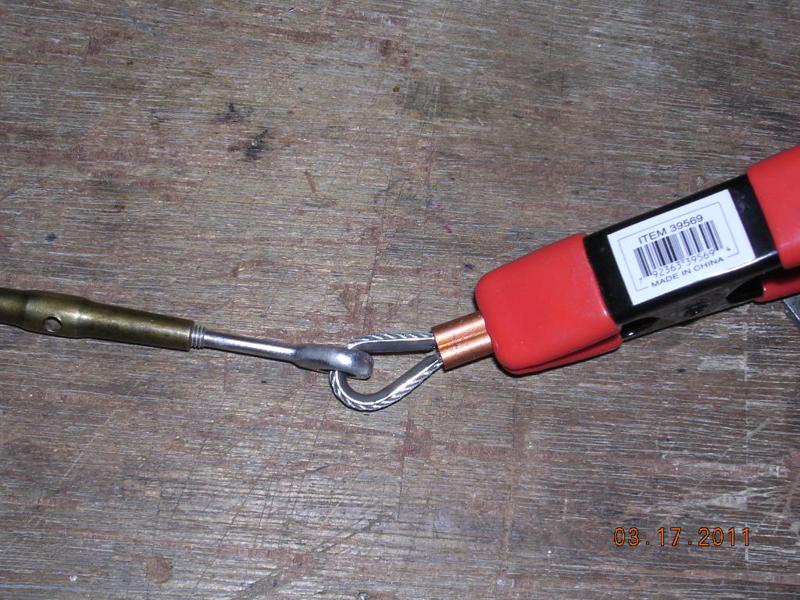
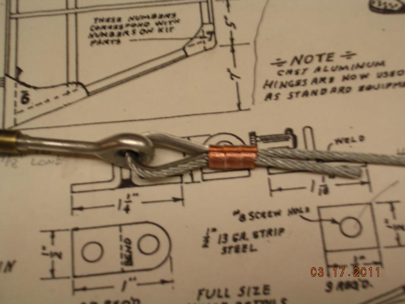
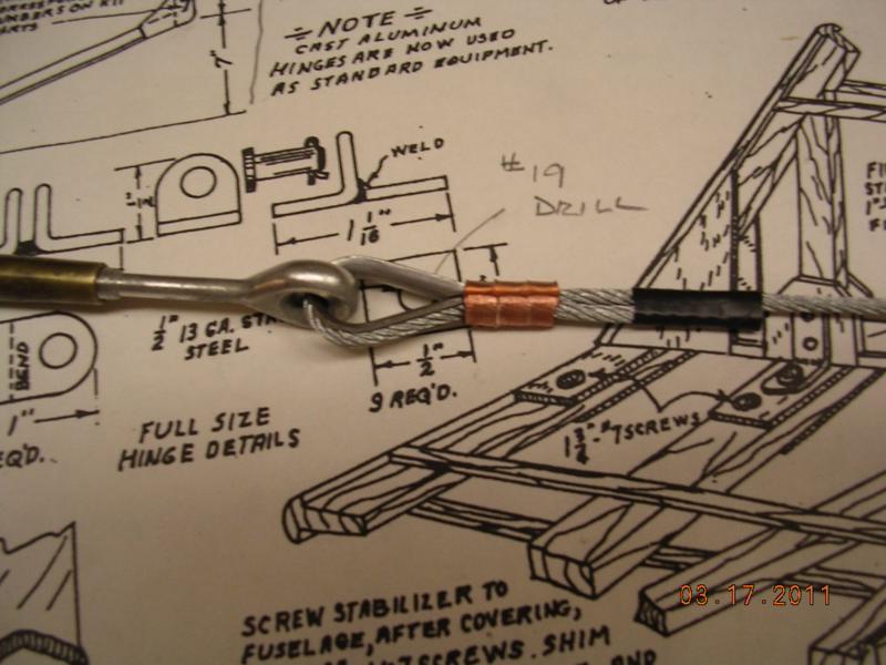
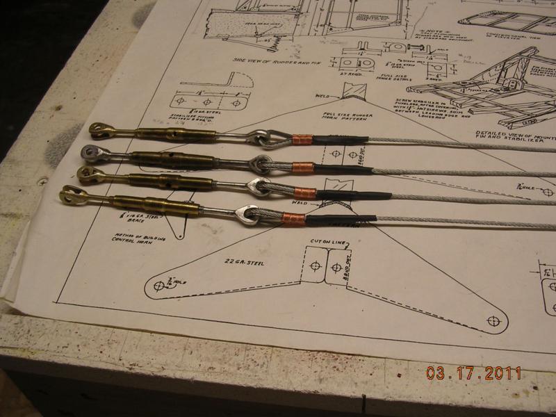
| Elected not to use washers, capped
bearings instead. String stretches too much, will use cable |
 |
 |
|
|
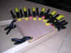
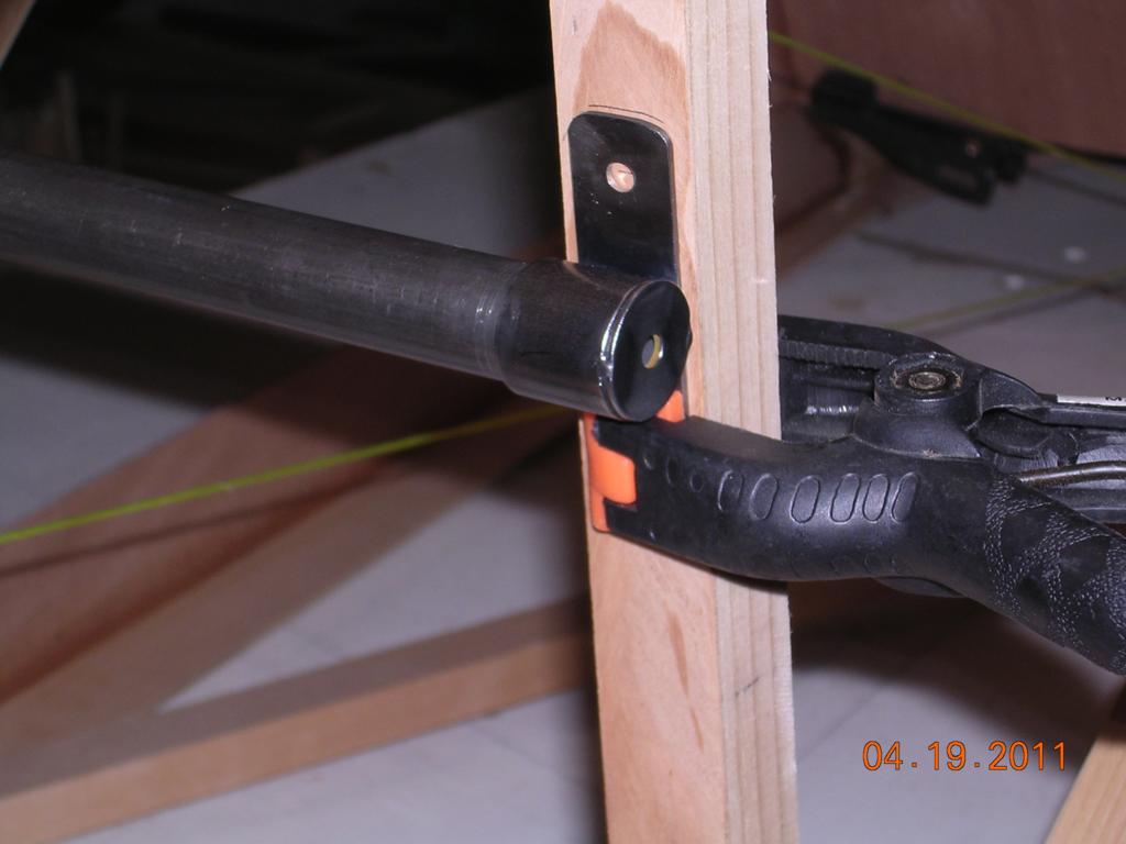
| Ready for oven |
Need bigger oven |
|
|
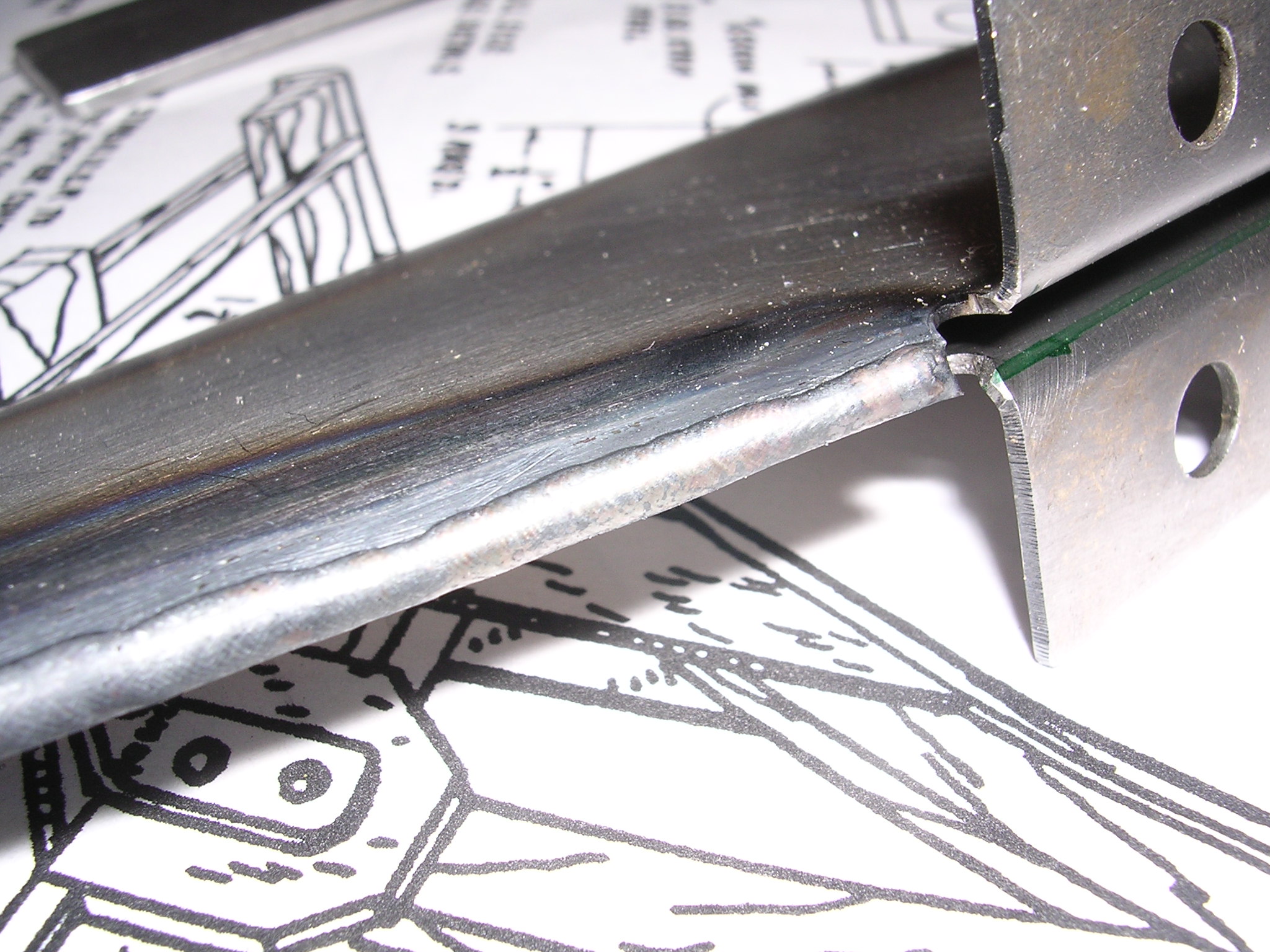
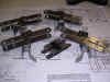
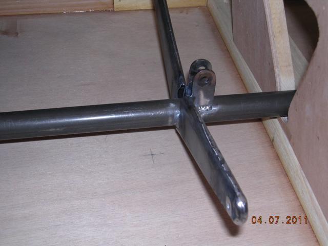
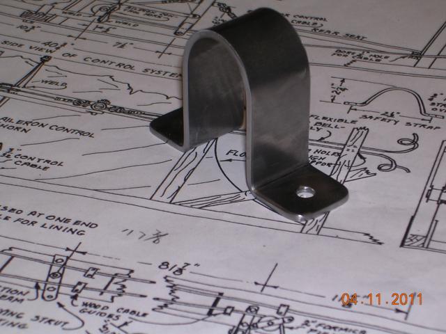
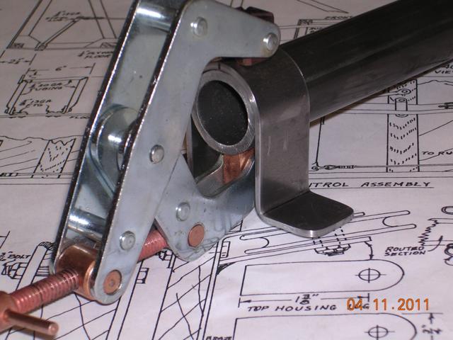
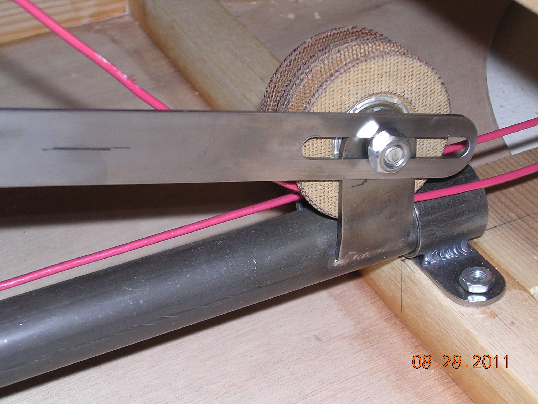
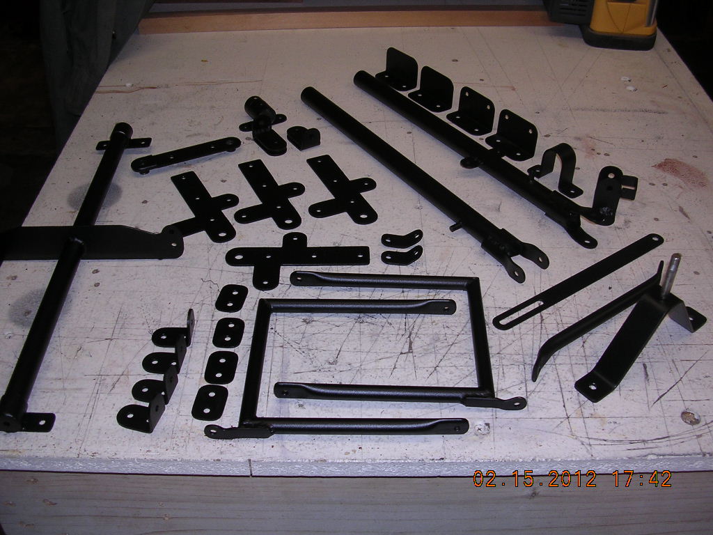
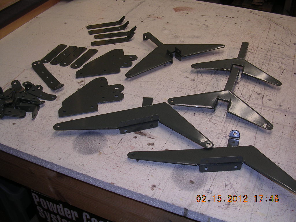
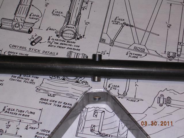
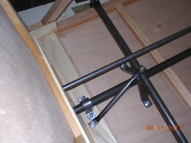
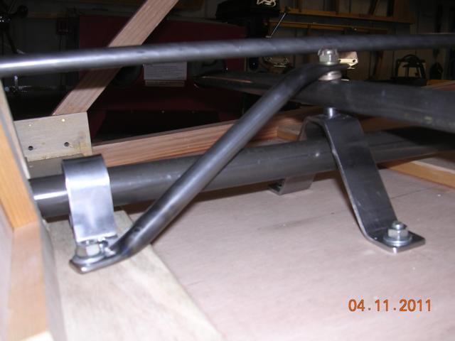
| CONSTRUCTION PHOTOS
(Controls) |
 |
 |
 |
 |
 |
 |
 |
 |
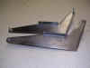
| Front torque bearing |
Aileron control horn |
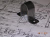
Safety strap formed over larger diameter
tube |
 |
 |
 |
 |
| Elevator Stop |
Powder Coated |
Elevator pulleys |
Plan to re-paint |
|
|
|
|
|
|
|
|
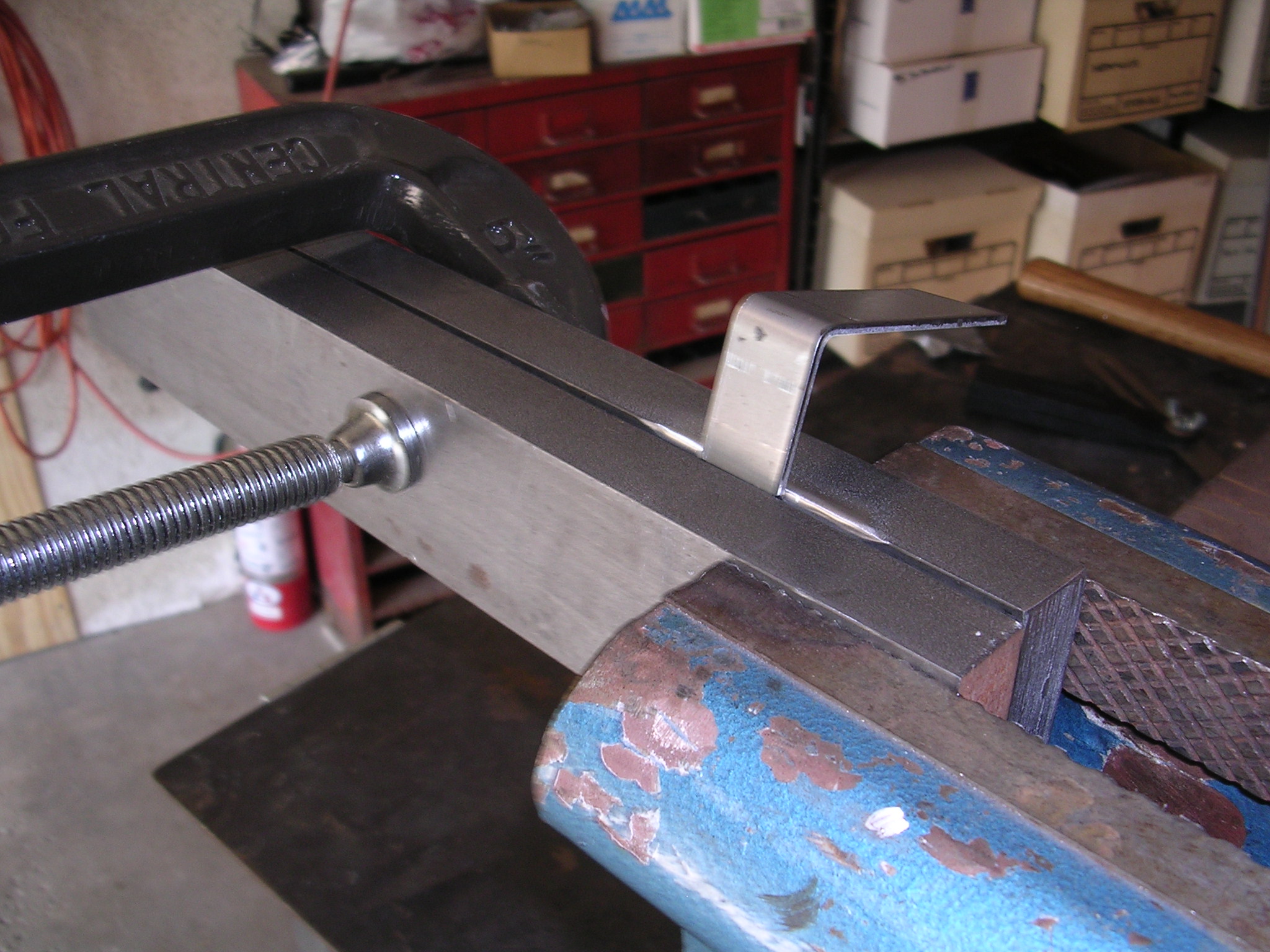
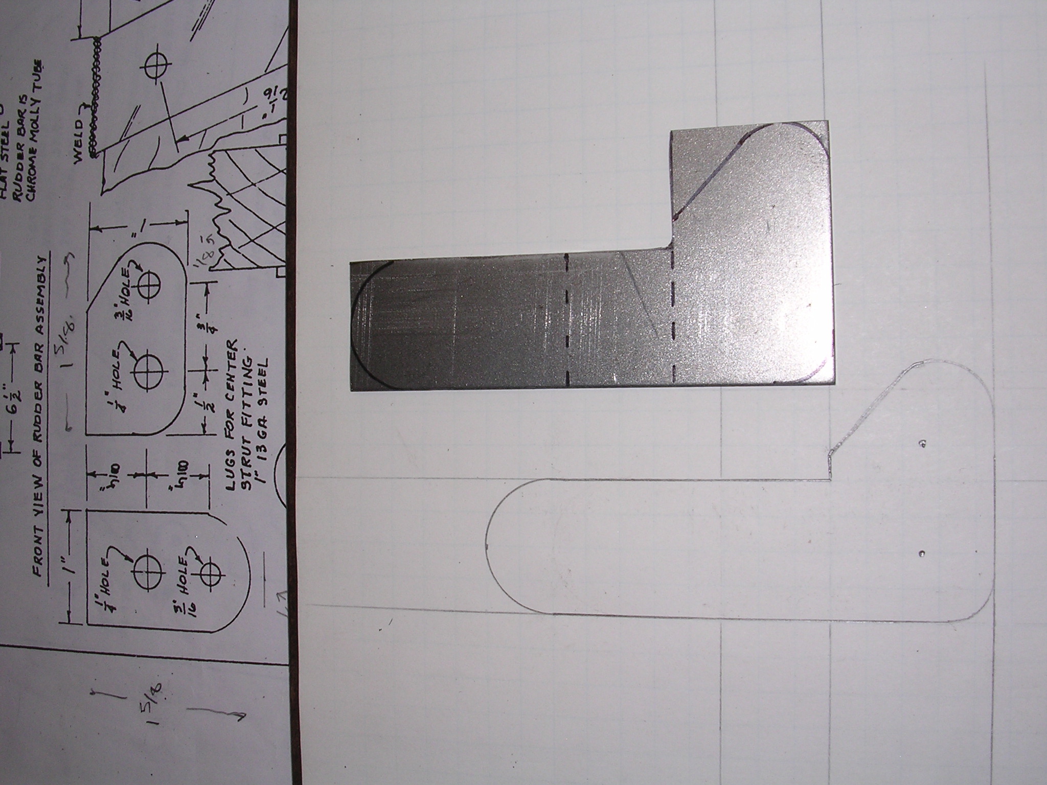
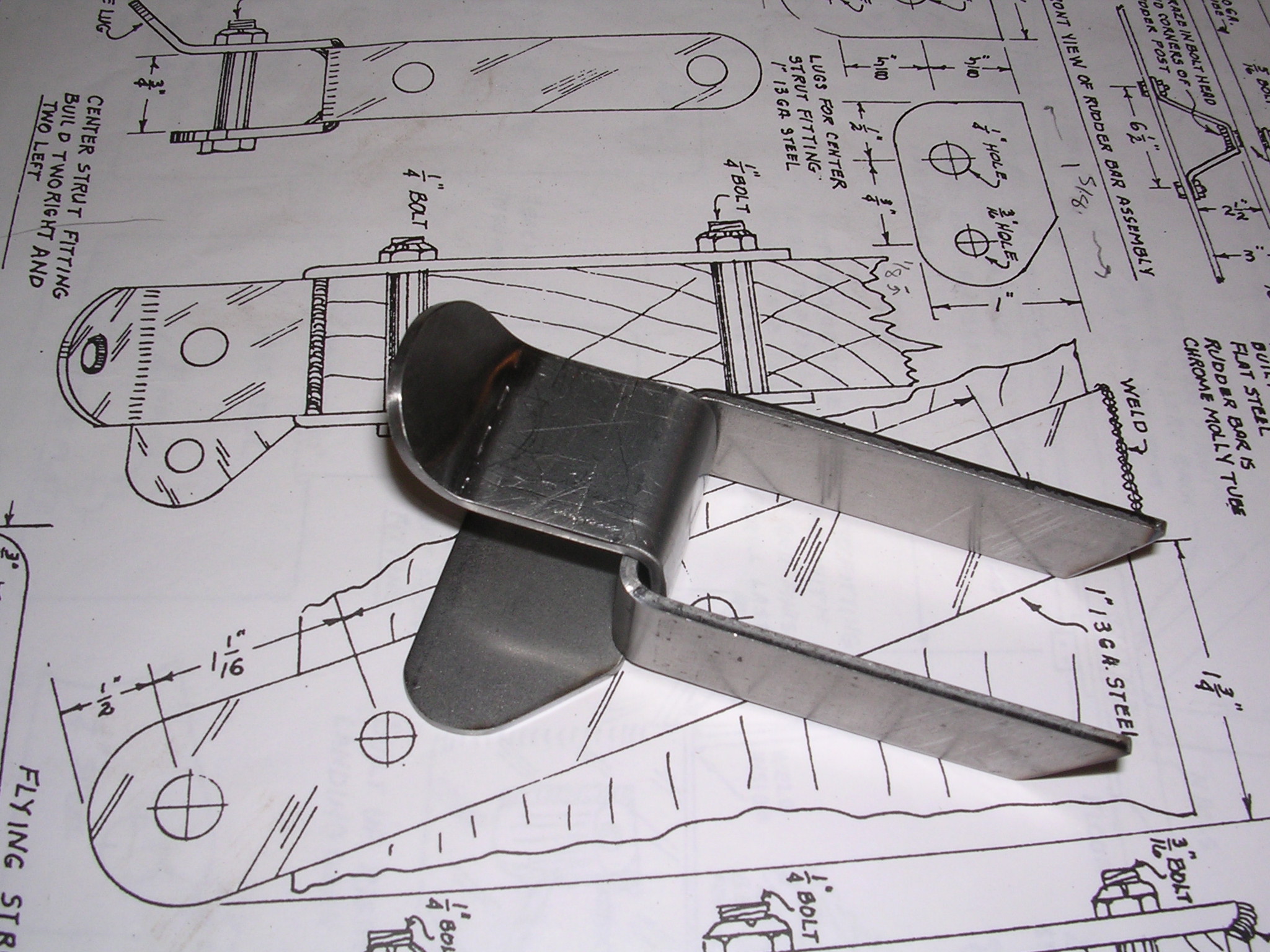
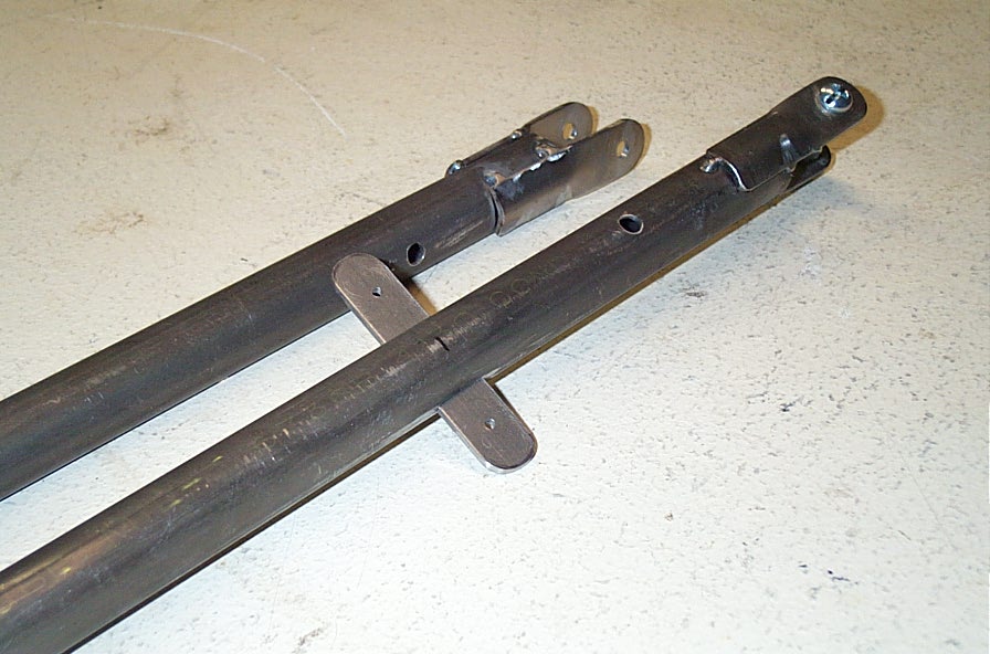
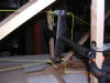
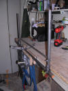
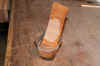
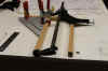
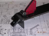
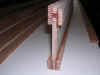
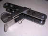
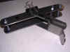
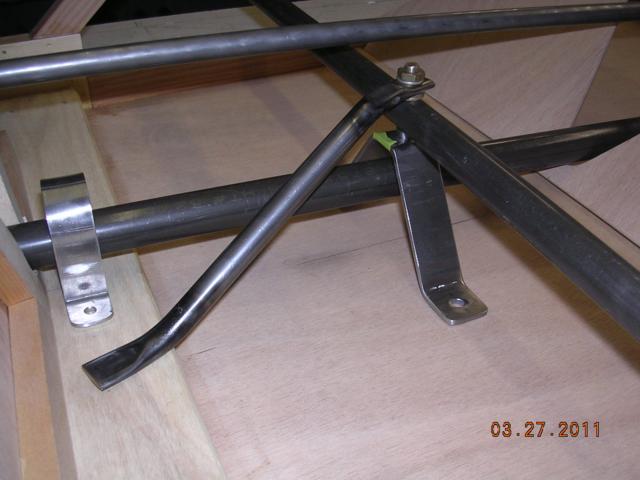
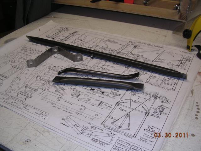
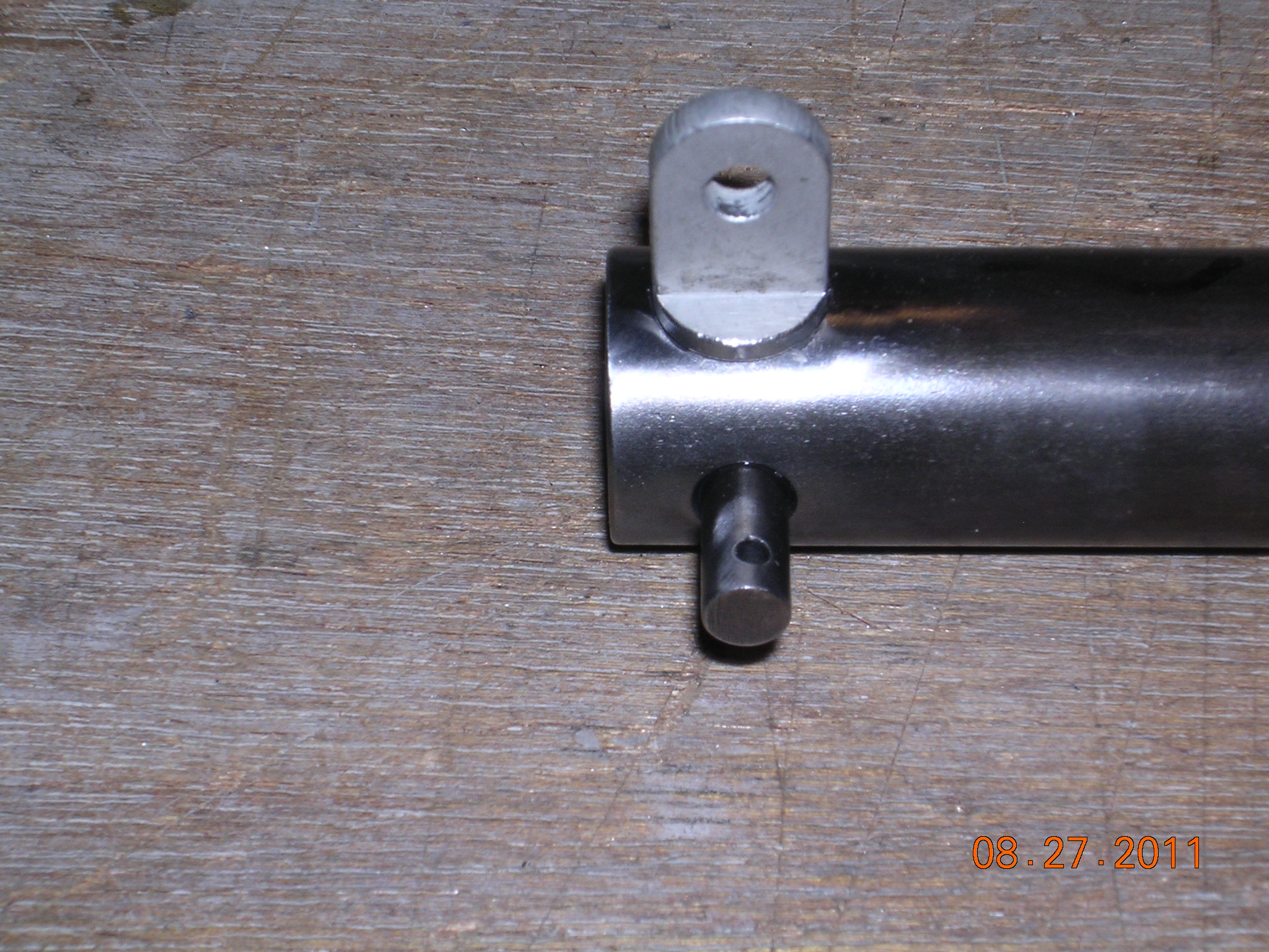
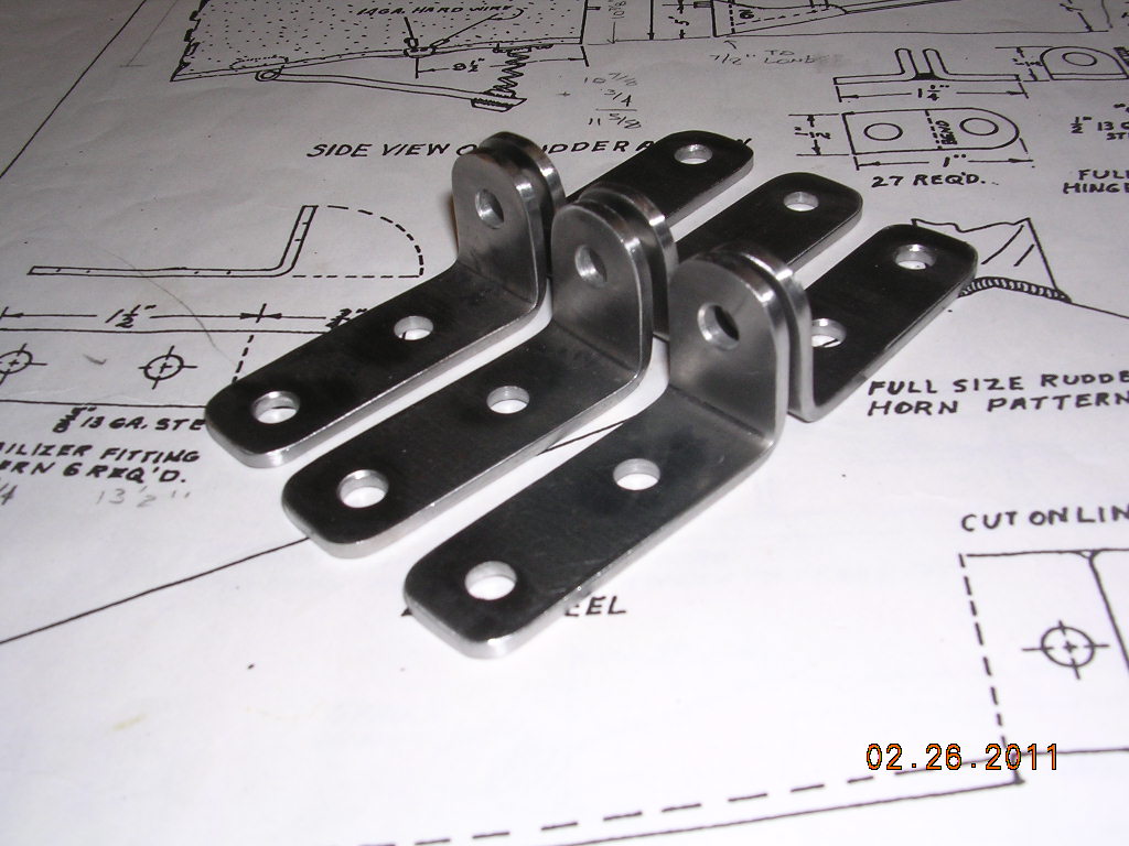
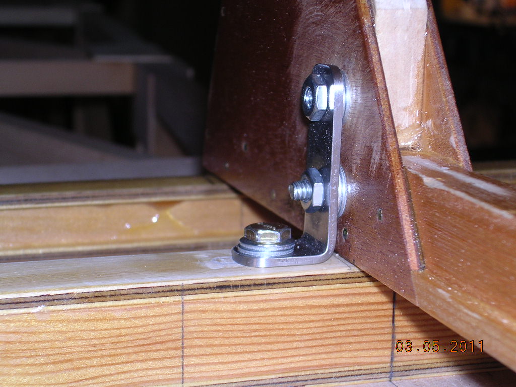
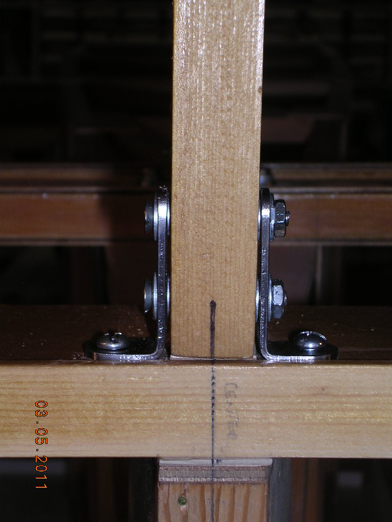
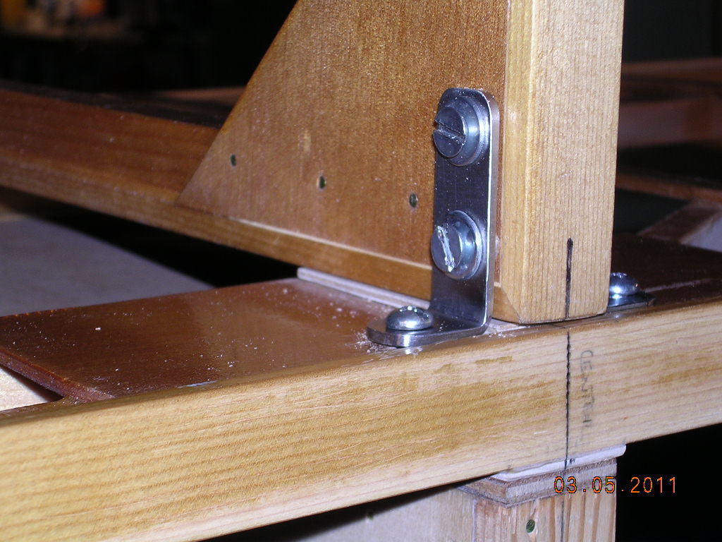
| CONSTRUCTION PHOTOS
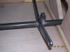
(Rudder Bar) |
 |
 |
 |
 |
| Trial fit |
|
|
Used 1/2" on left |
 |
 |
 |
 |
|
|
Tacked only |
|
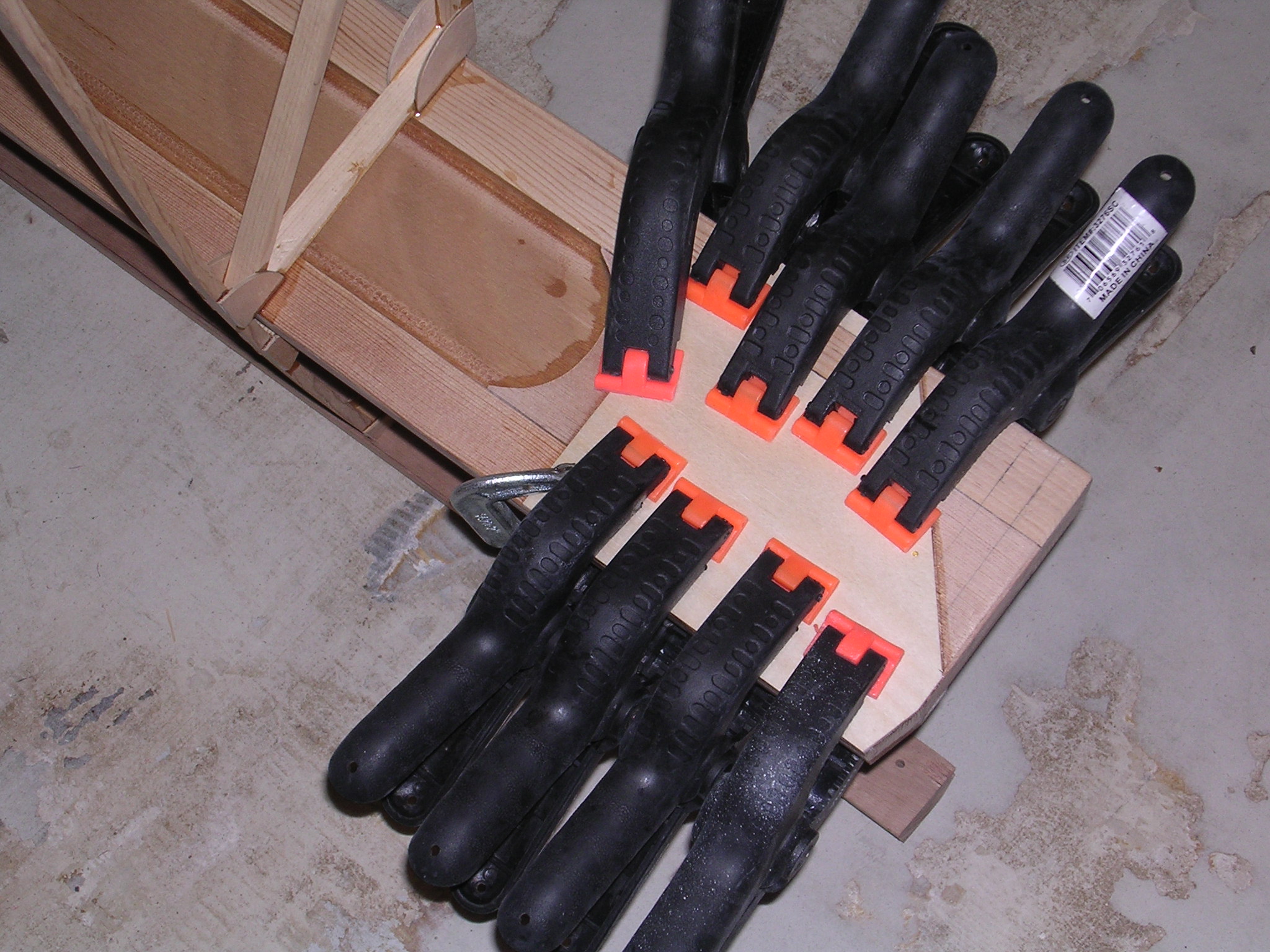
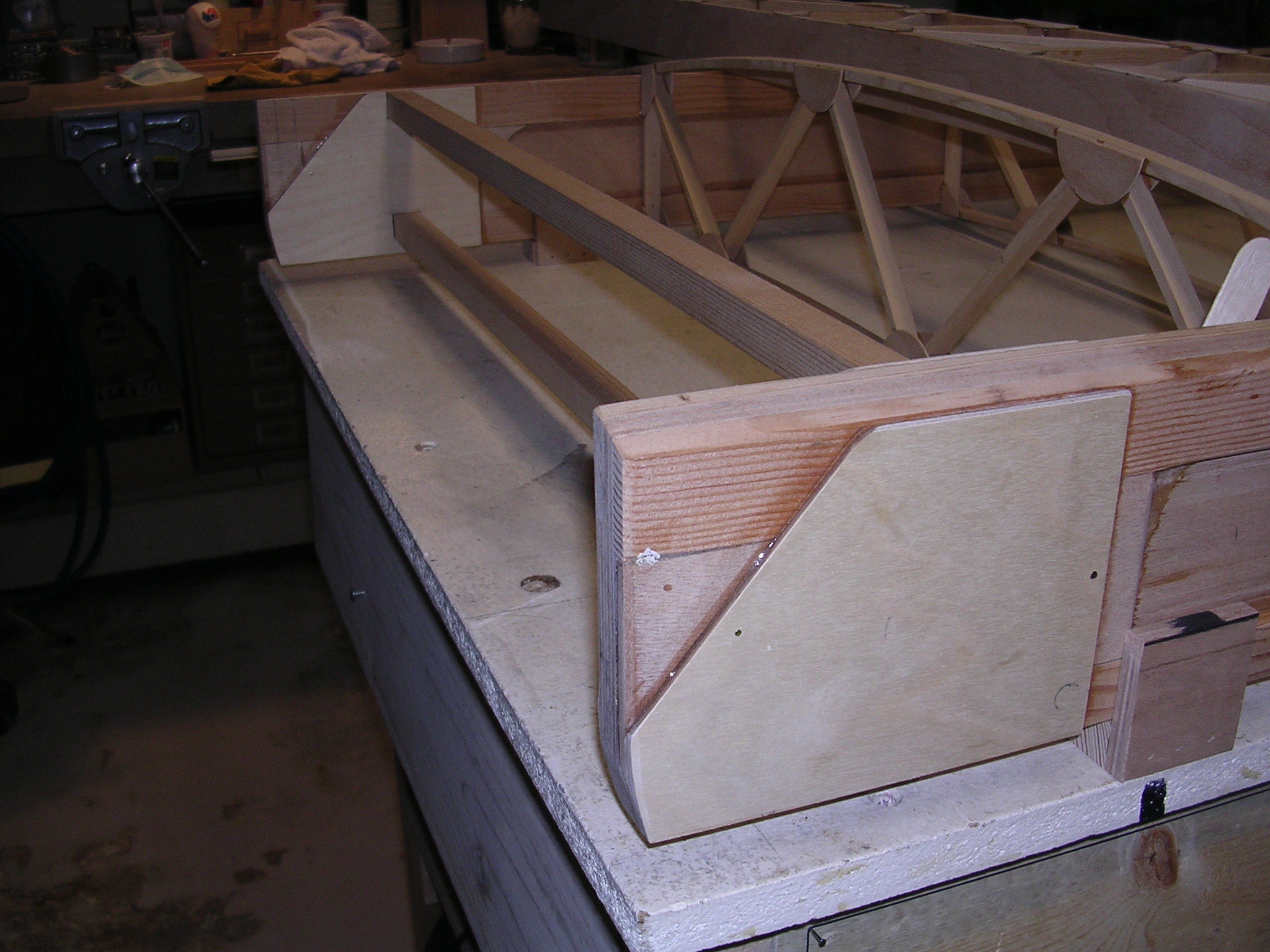
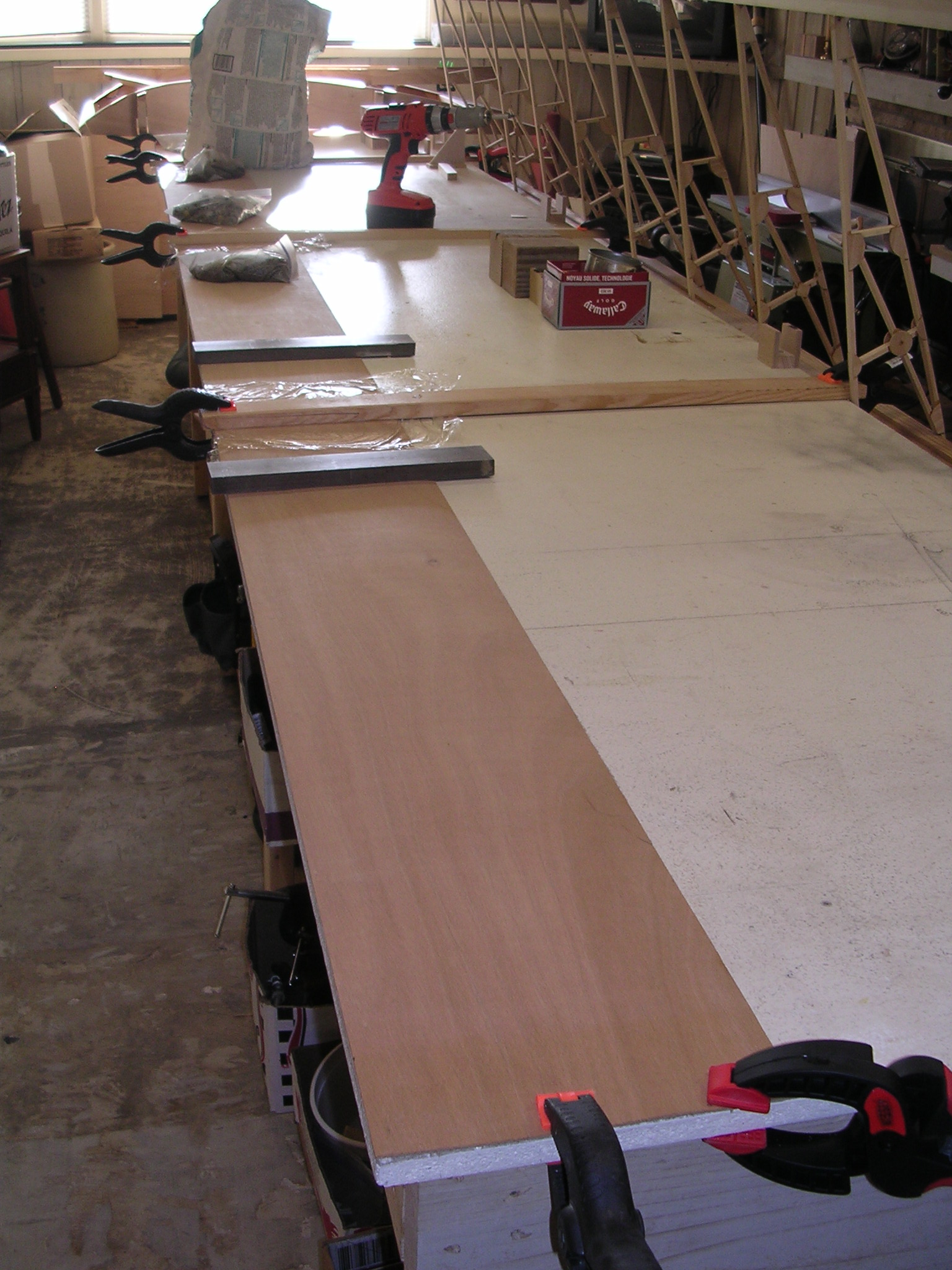
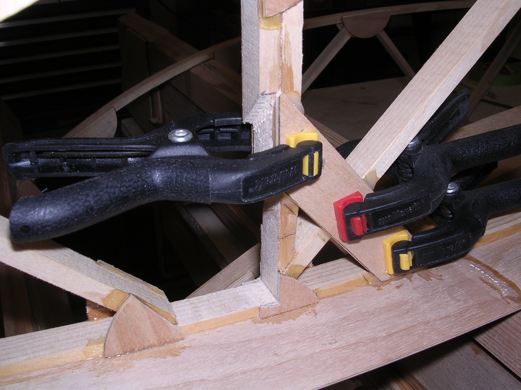
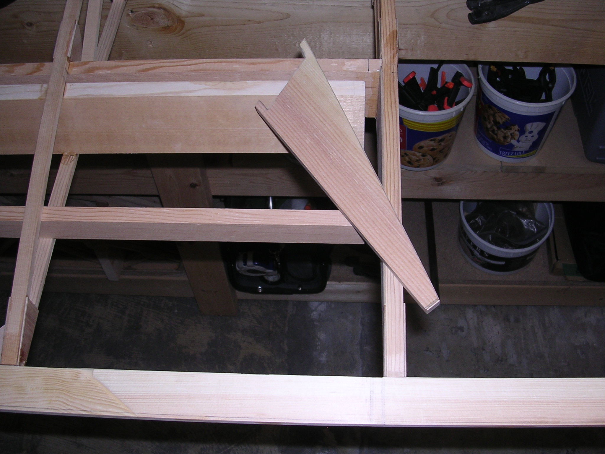
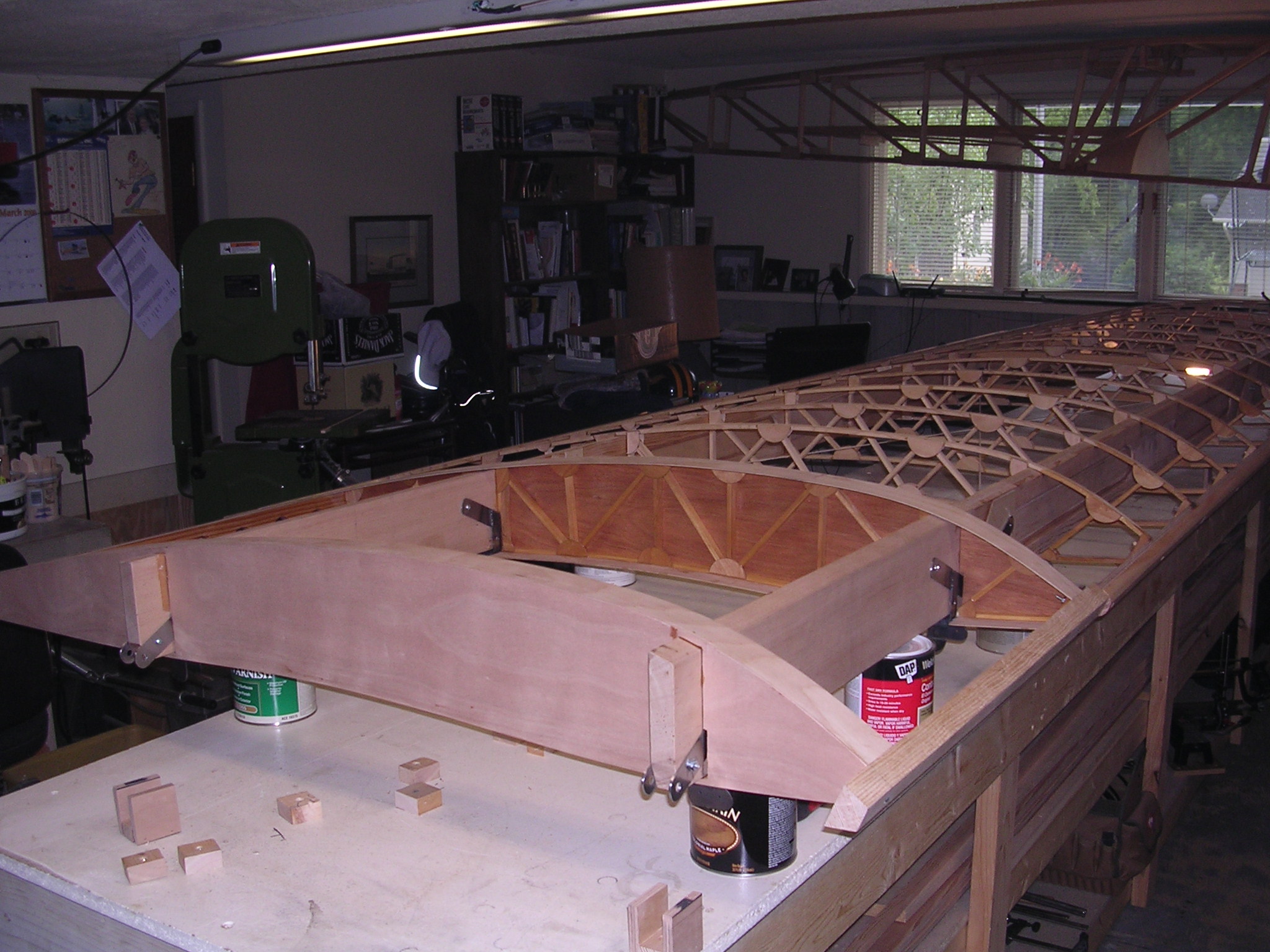
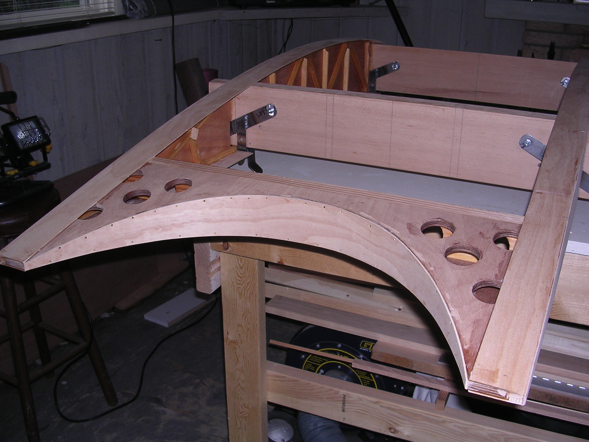
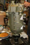
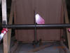
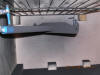
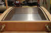
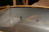
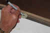
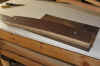
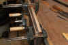
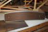
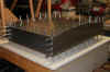
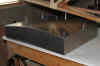
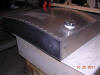
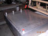
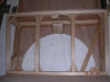
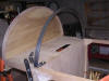
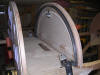
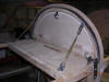
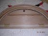
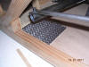
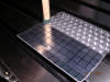
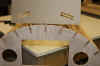
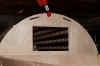
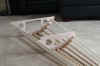
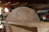
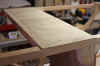
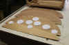
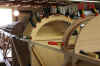
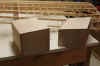
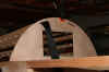
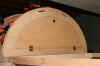
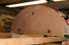
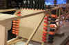
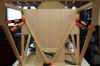
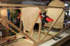
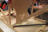
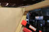
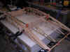
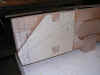
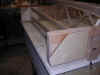
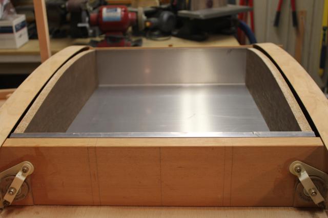
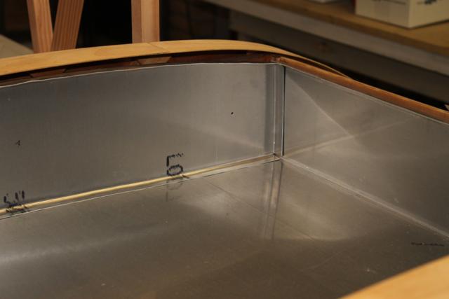
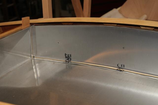
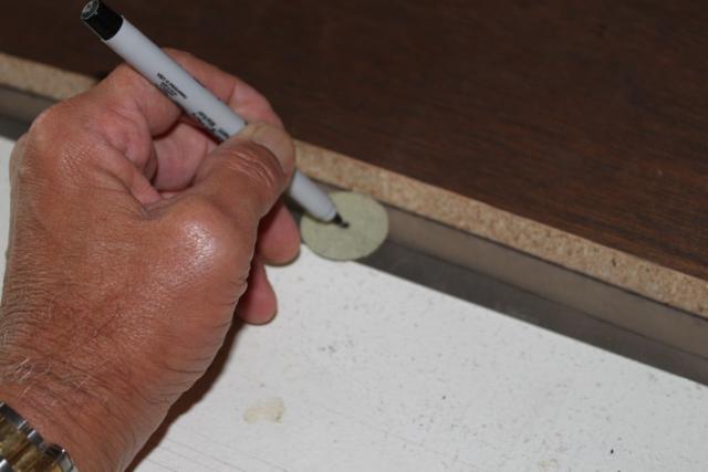
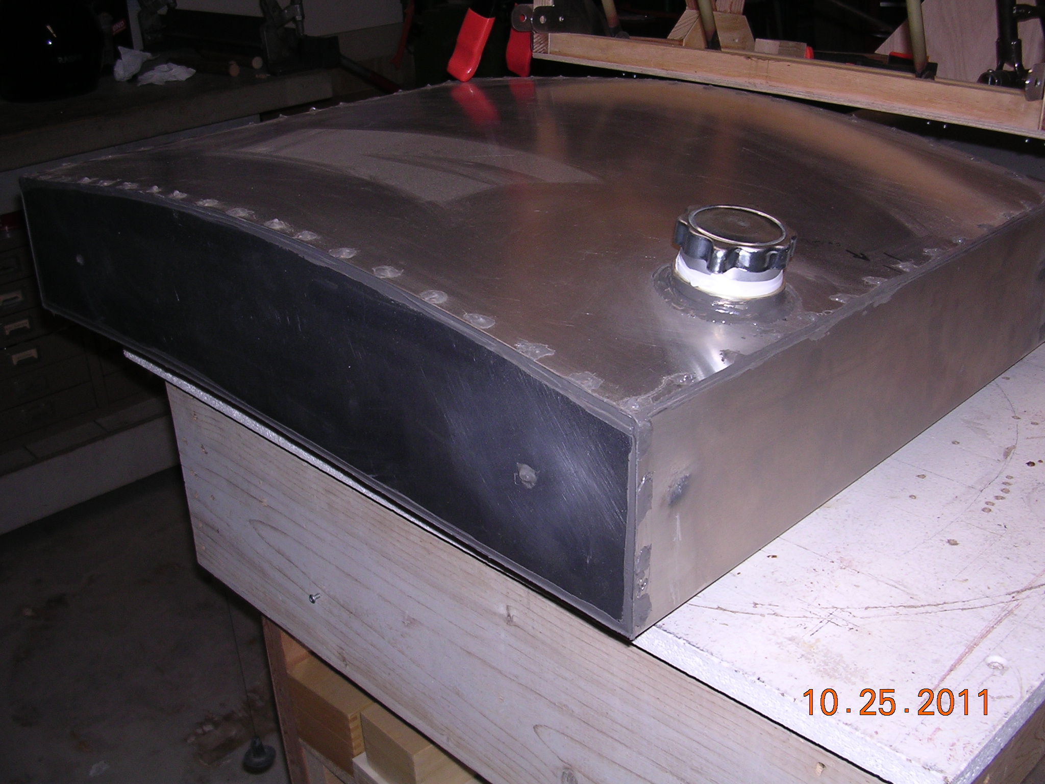
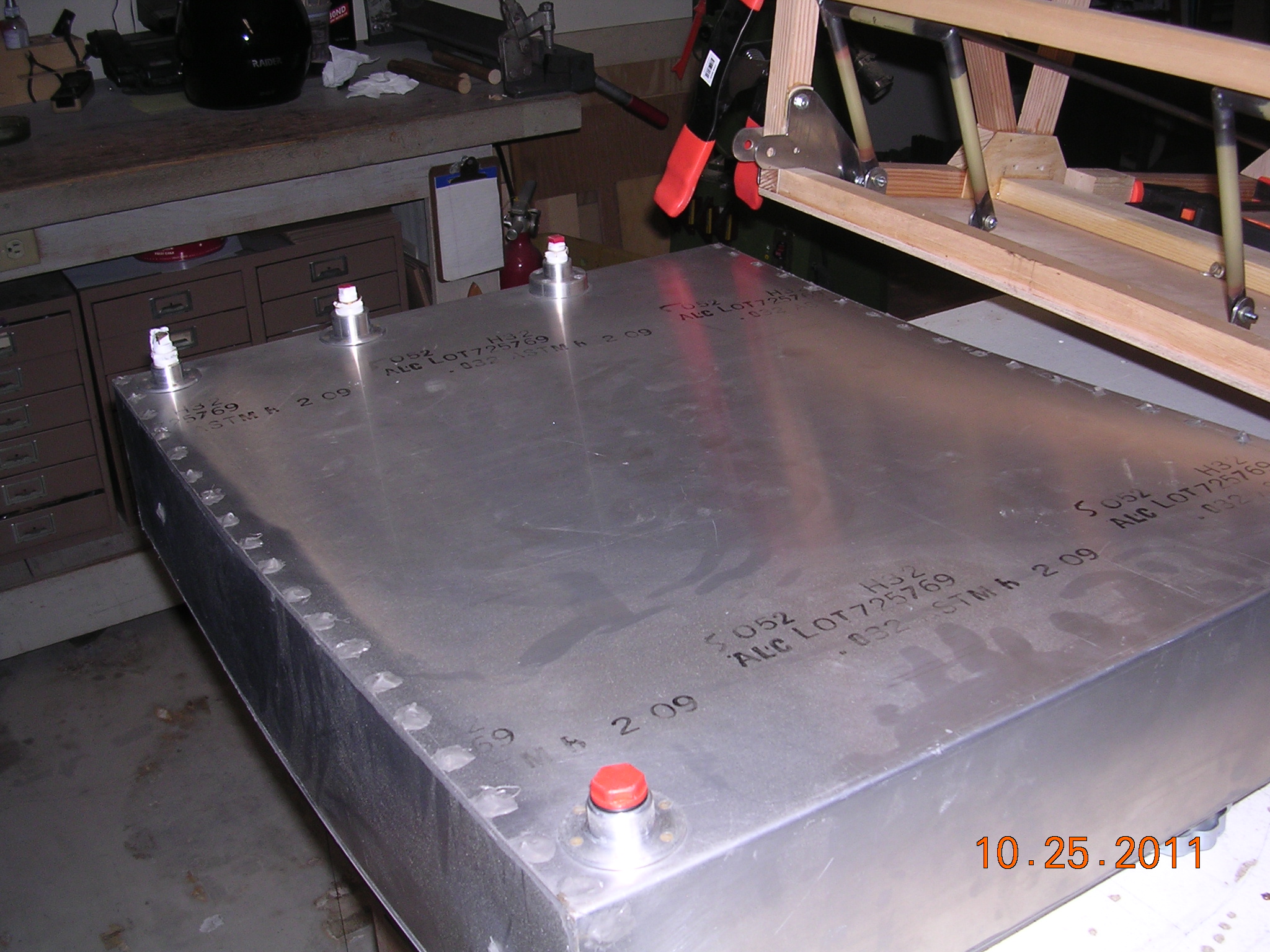
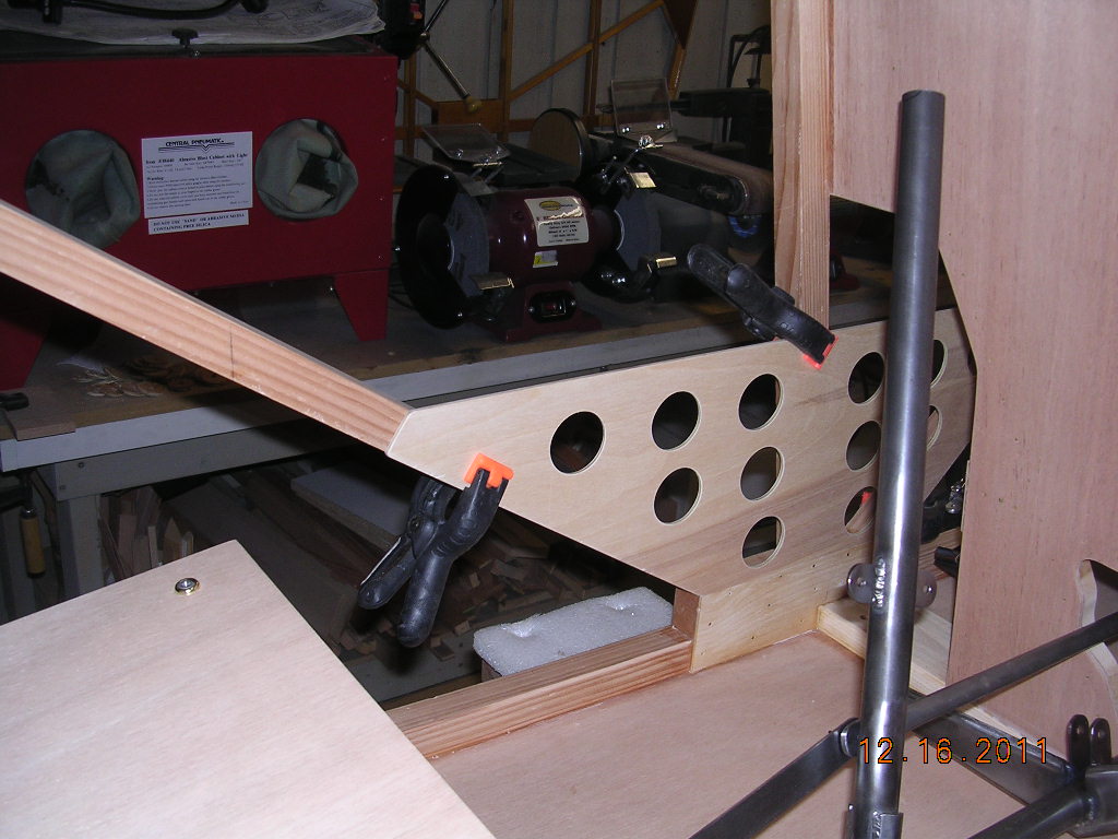
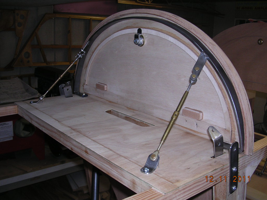
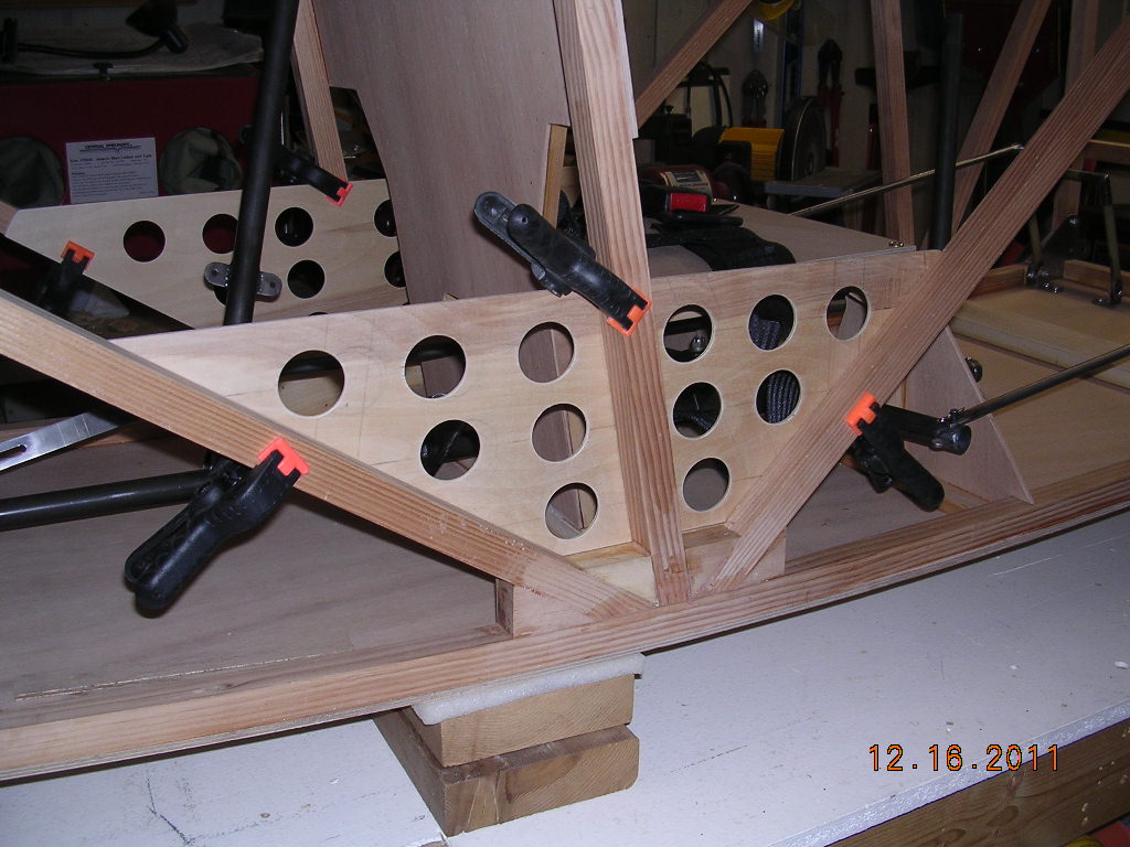
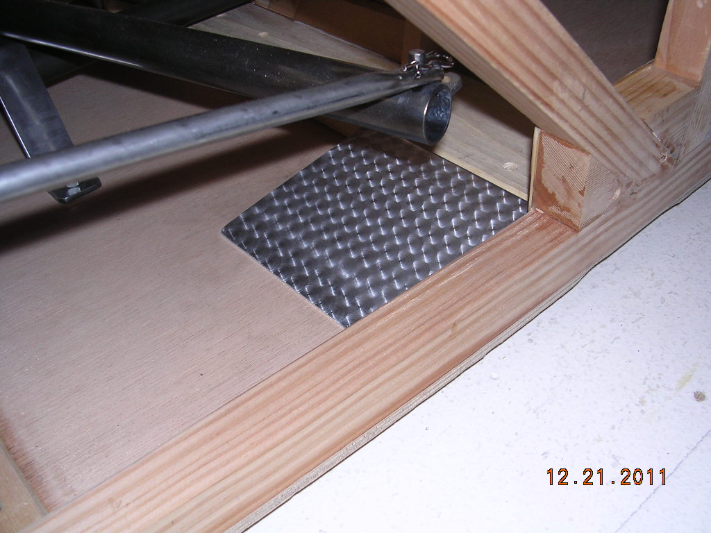
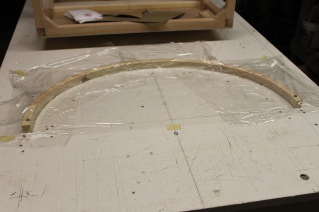
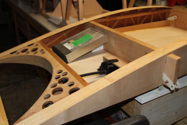
| CONSTRUCTION PHOTOS
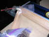
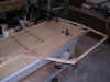
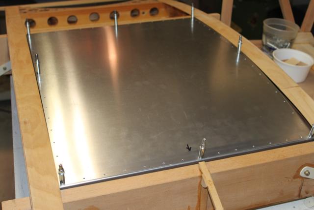
(Center Section Tank) |
 |
 |
 |
 |
 |
 |
 |
 |
 |
 |
 |
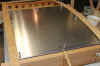 |
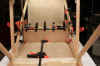
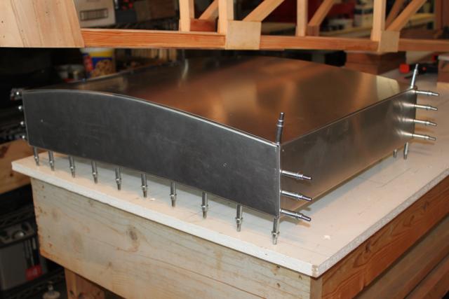
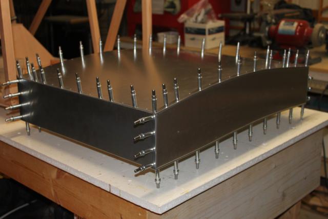
| .032x21"x27"x5"=13 gallons
aprox, riveted and Prosealed |
 |
 |
 |
 |
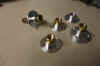
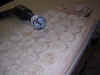
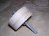
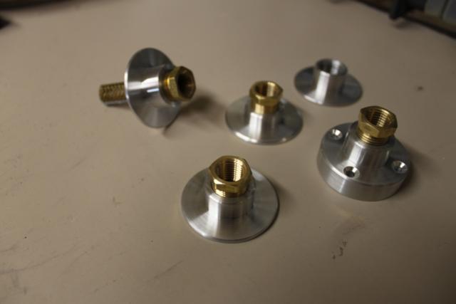
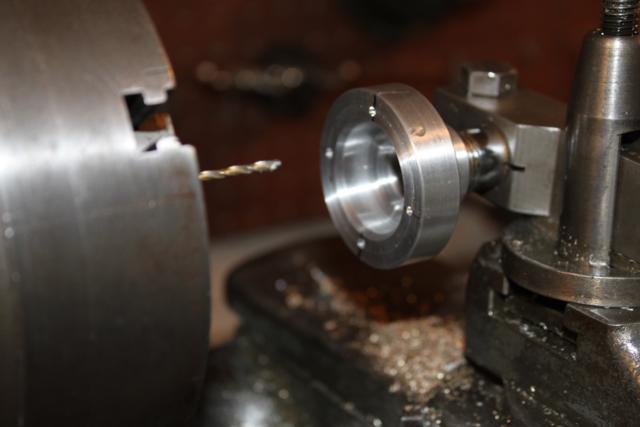
| Turned fuel fittings |
Indexing on Lathe |
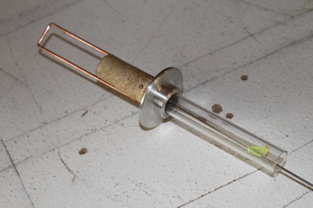
Fuel float trial didn't use |
Used this one |
|
|
|
|
|
|
|
|
|
 |
 |
|
|
|
|
|
|
|
|
|
|
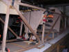
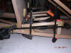
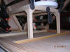
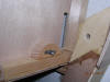
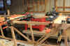
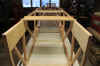
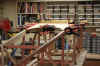
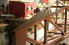
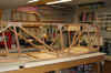
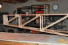
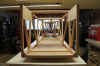
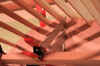
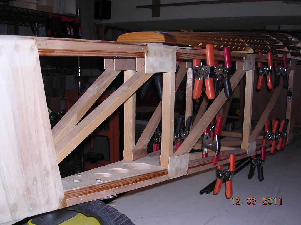
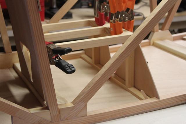
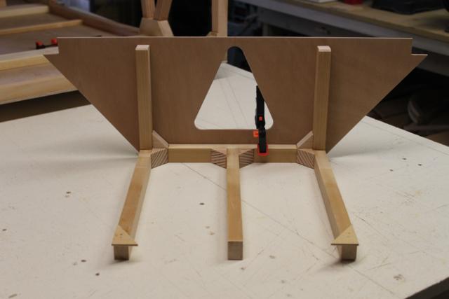
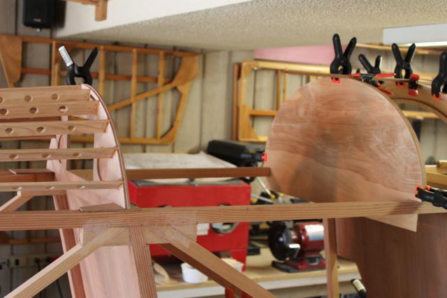
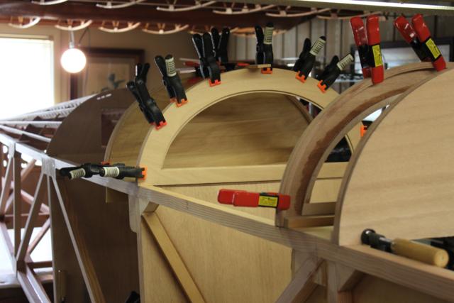
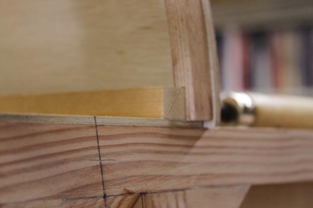
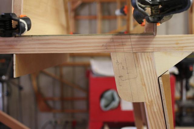
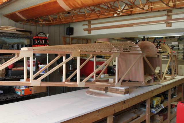
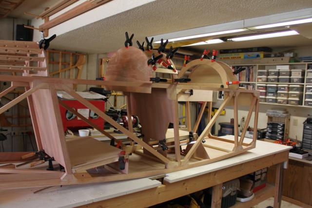
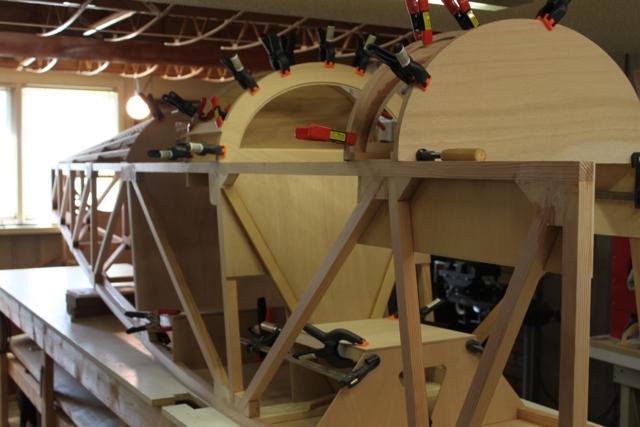
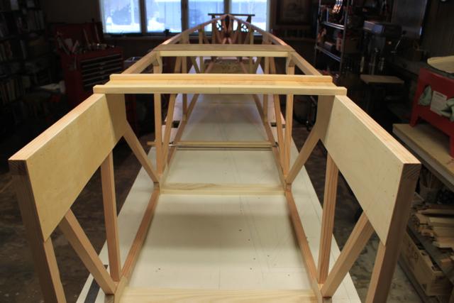
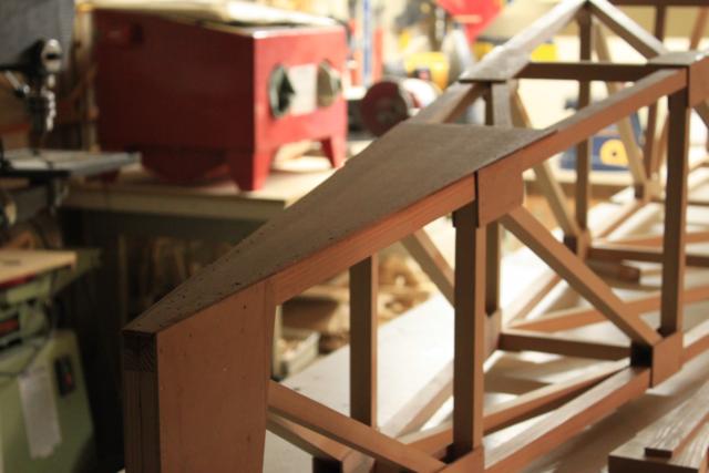
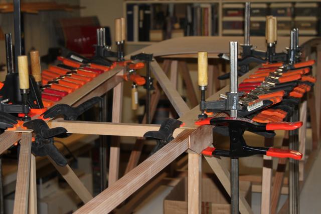
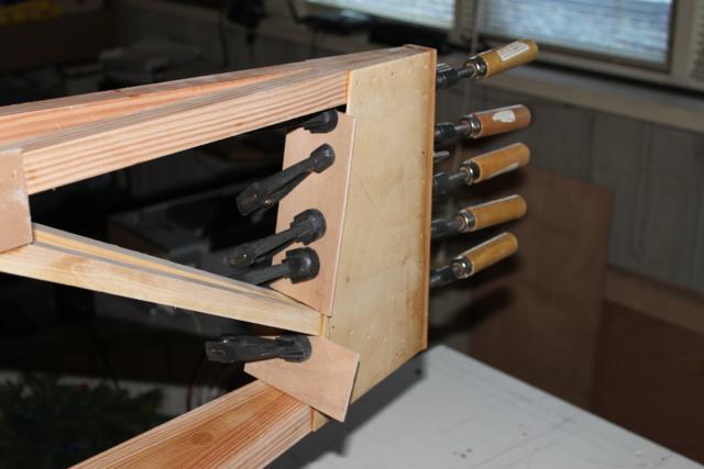
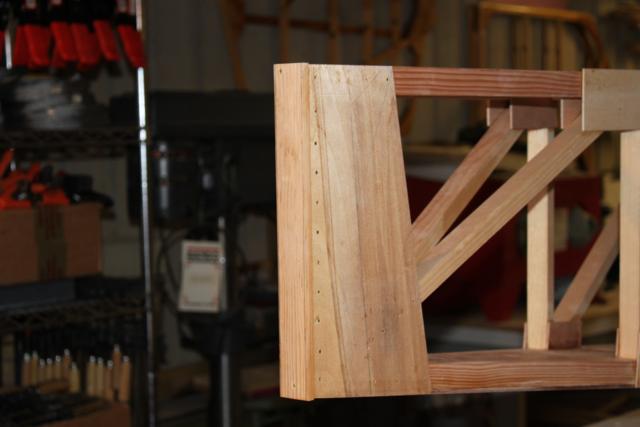
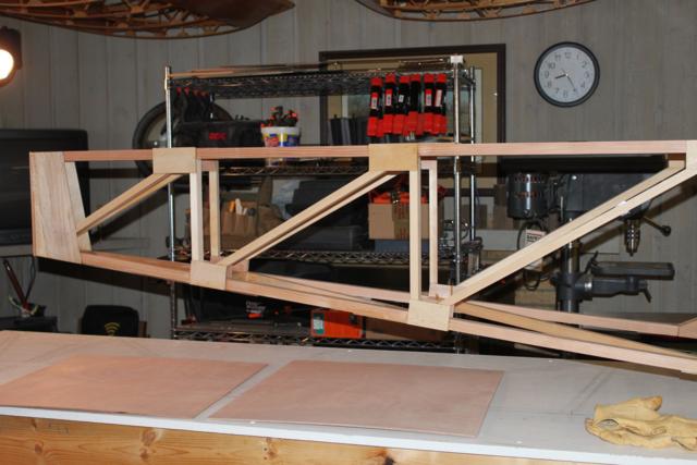
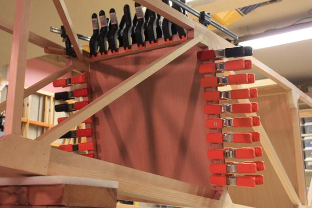
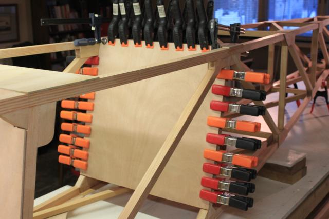
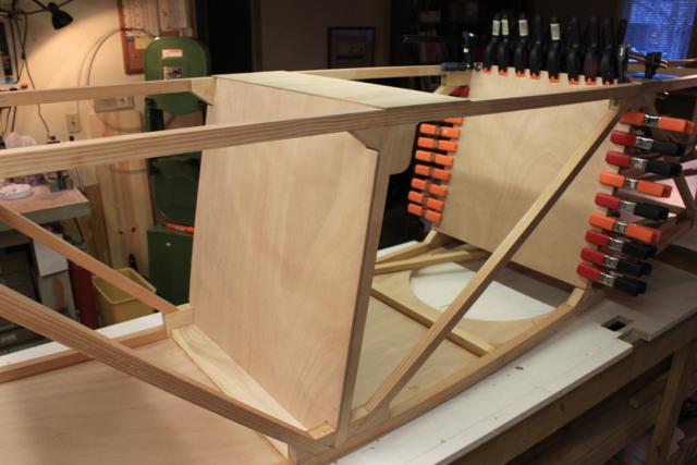
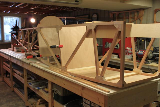
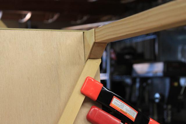
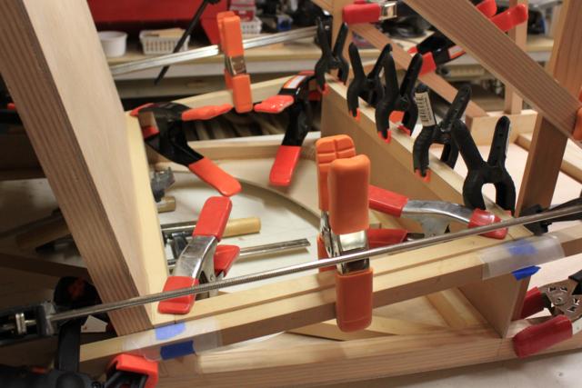
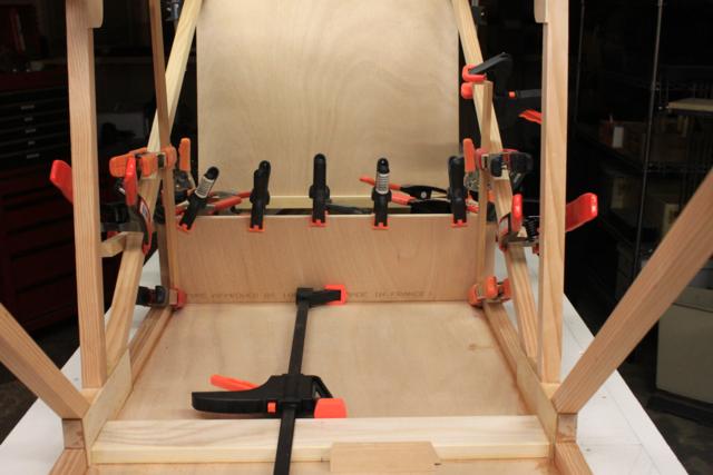
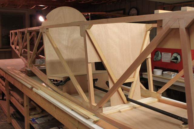
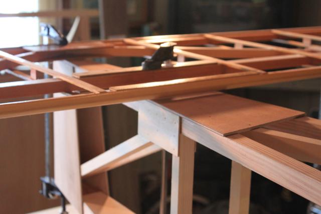
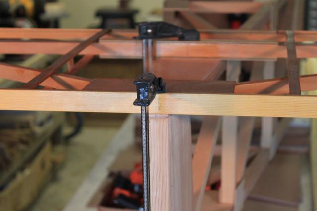
| CONSTRUCTION PHOTOS (Fuselage) |
 |
 |
 |
 |
 |
 |
 |
 |
 |
 |
 |
 |
 |
 |
 |
 |
 |
 |
 |
 |
|
|
|
|
 |
 |
 |
 |
 |
 |
 |
 |
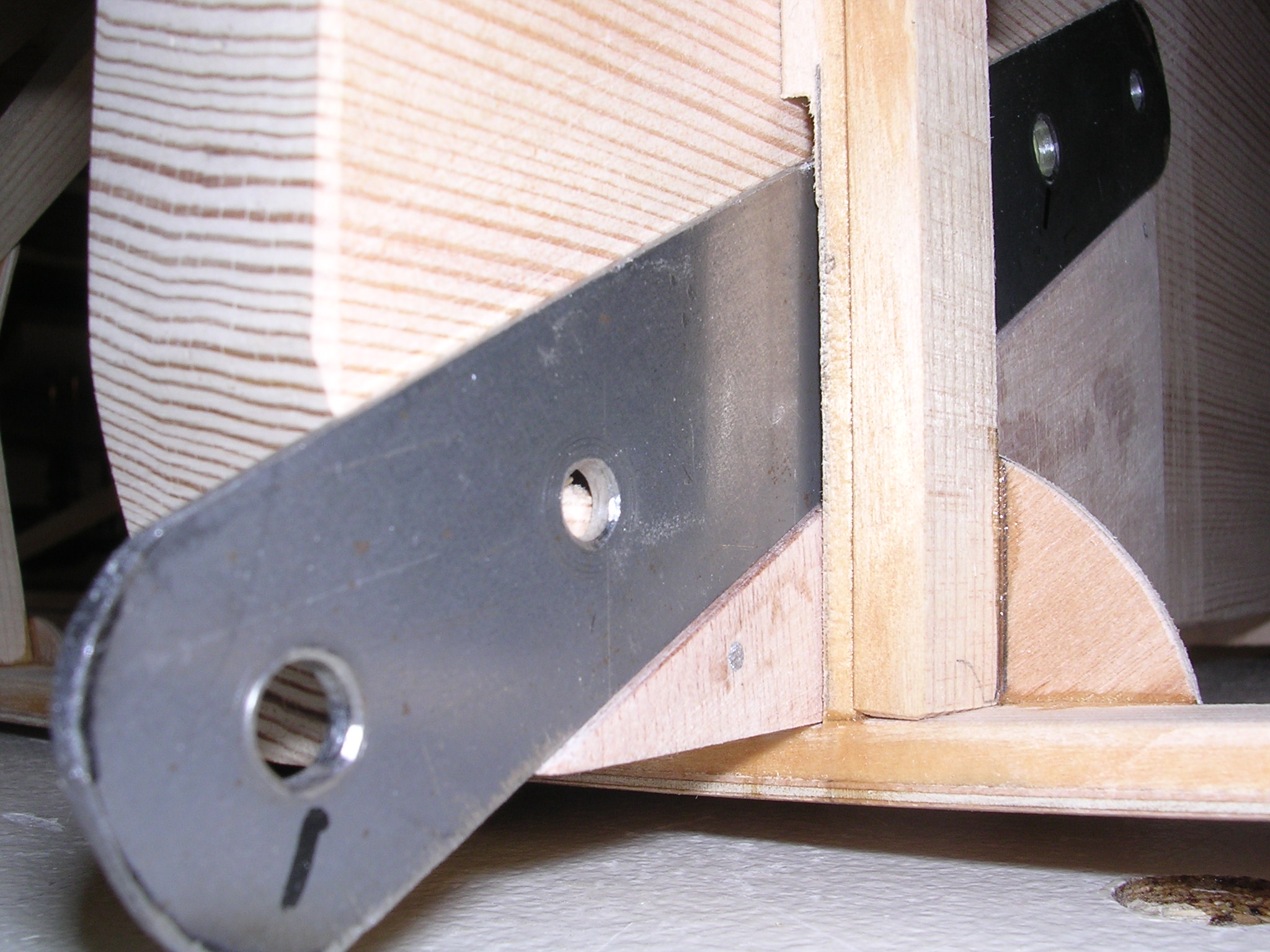
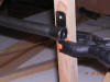
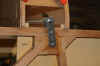
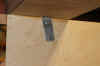
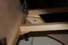
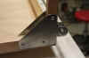
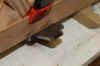
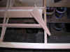
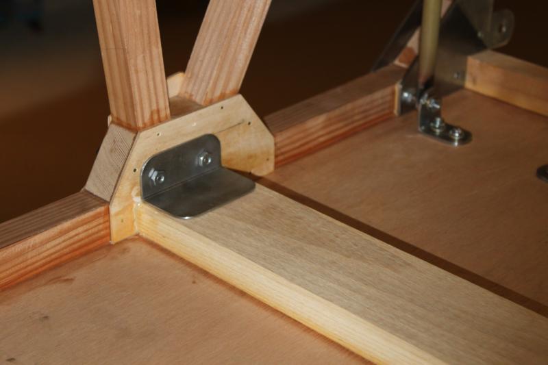
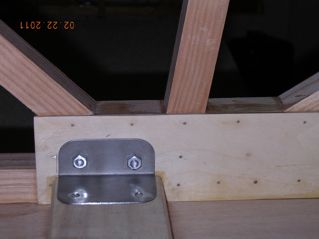
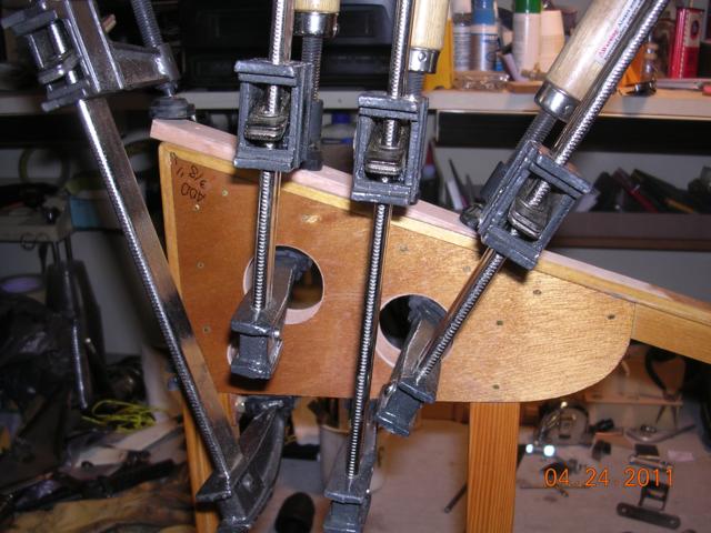
| .090 cabane lower fittings, after fitting
side ply will drill from inside out |
|
|
|
|
|
|
|
|
|
|
|
|
 |
 |
 |
 |
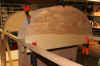
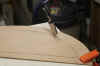
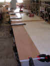
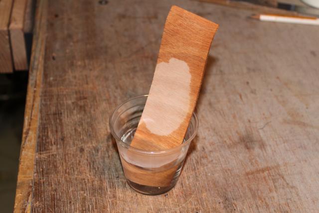
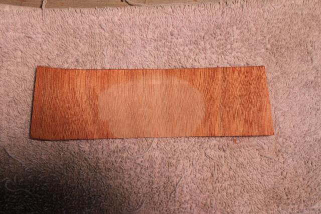
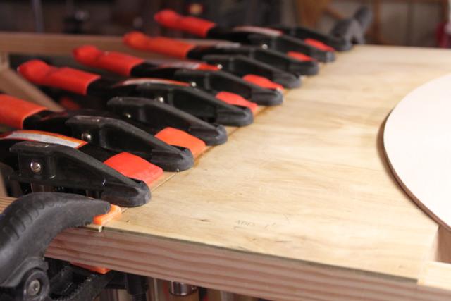
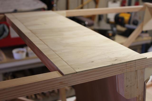
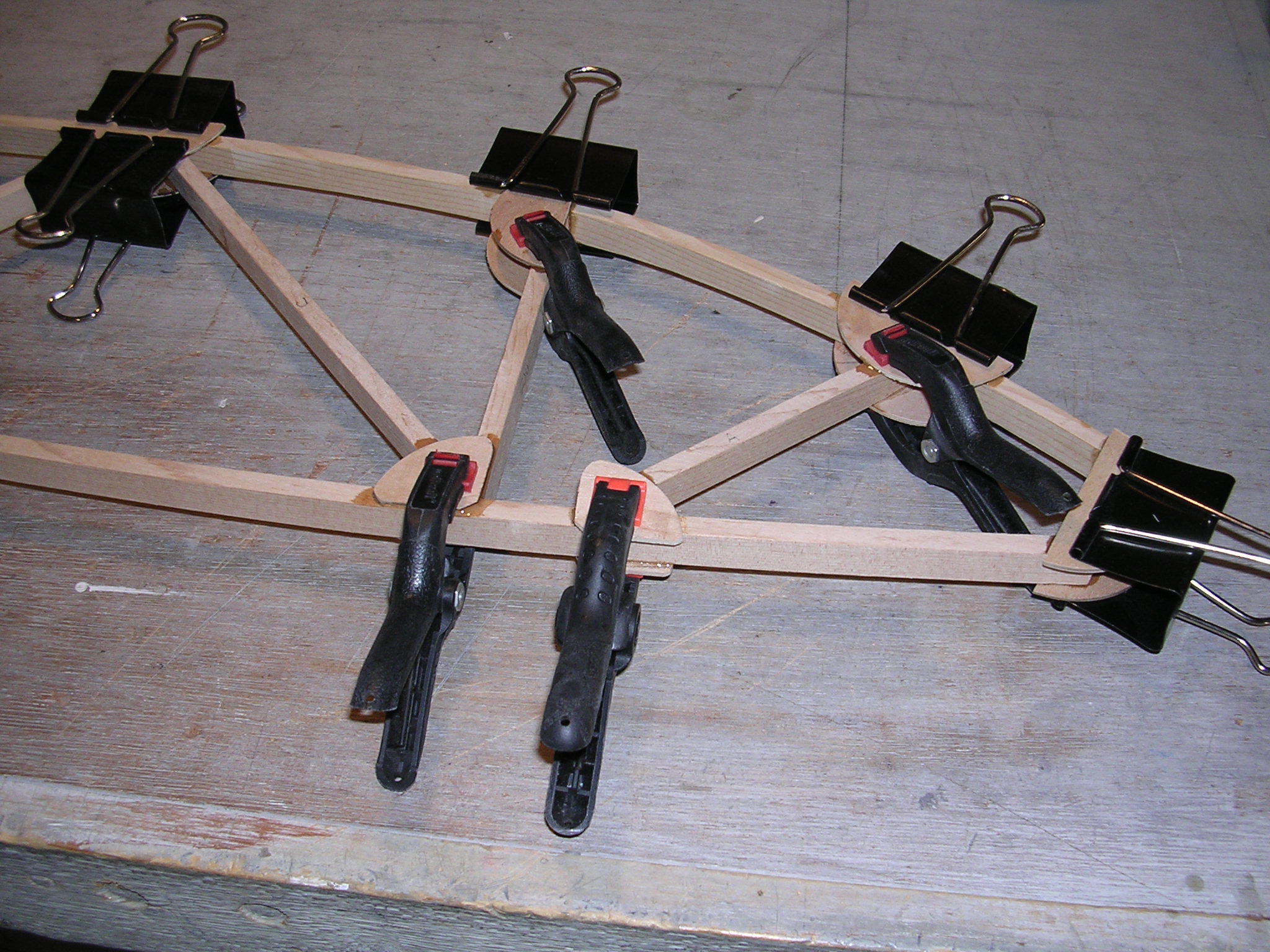
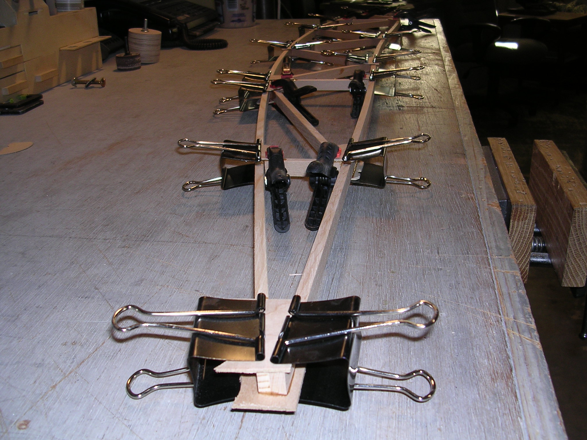
| Soaking 1/16" ply |
1/16" Okume |
Nice bend |
|
 |
 |
 |
 |
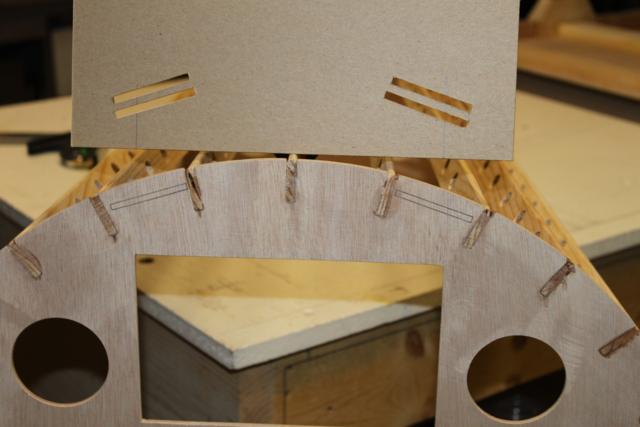
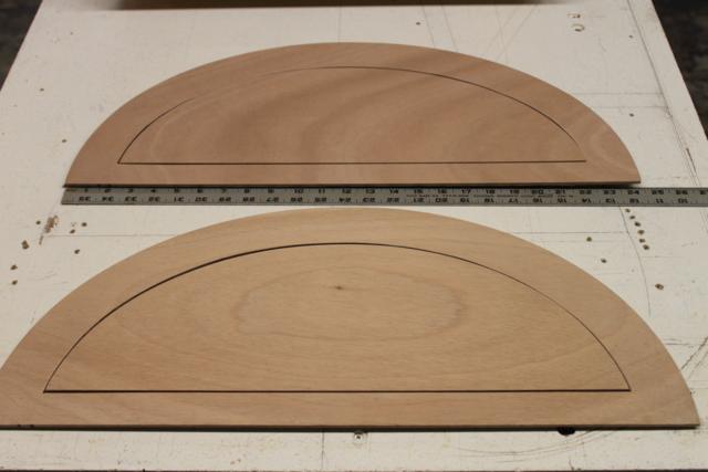
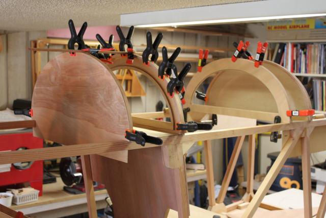
| Template |
Belt but-outs |
Brace for 90 degrees |
|
 |
 |
 |
 |
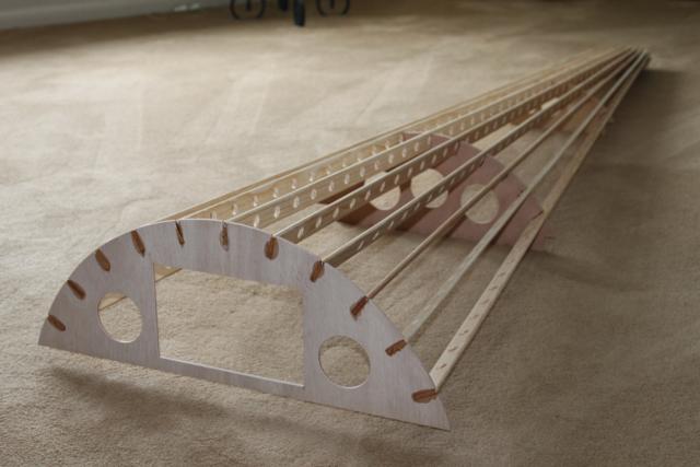
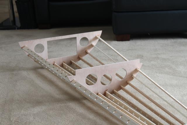
| 11 stringers |
375 lightening holes |
|
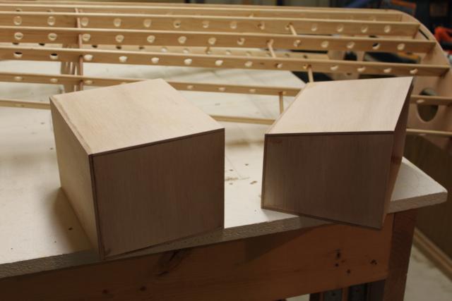
Helmet box |
 |
 |
 |
 |
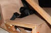
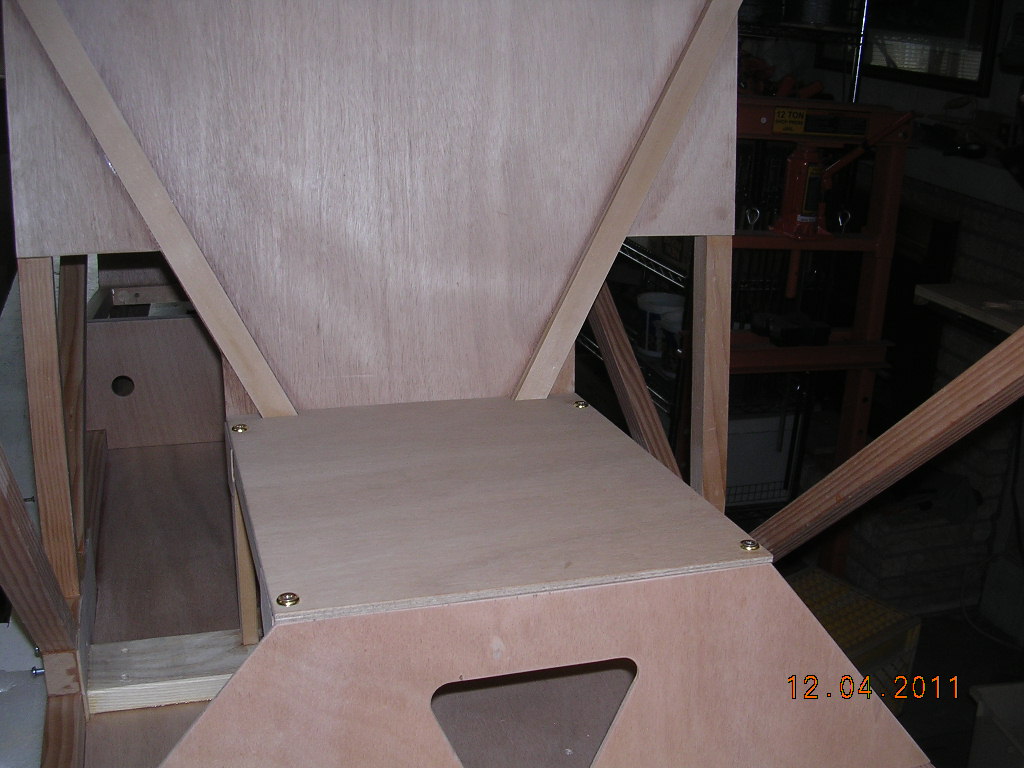
| Front seat back |
F-seat supports |
More F-seat bottom |
Front seat |
 |
 |
 |
 |
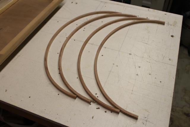
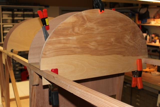
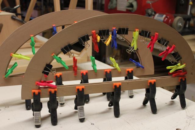
| Seat going together |
Brace form |
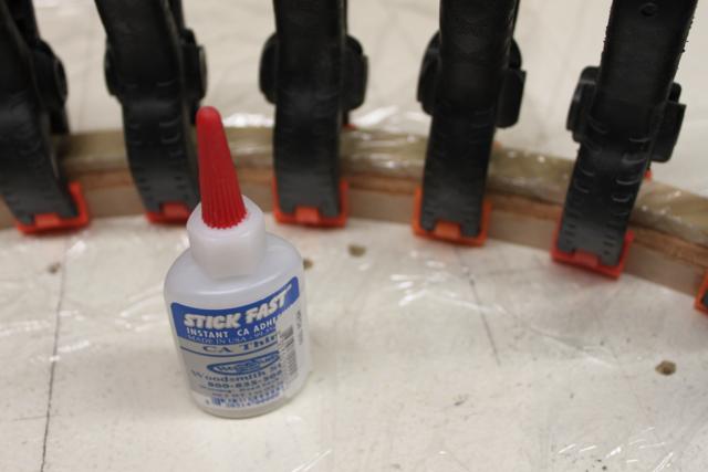
1/16 x 1/2 ply strips |
Thin super glue |
 |
 |
 |
 |
| Done |
Panel test fit |
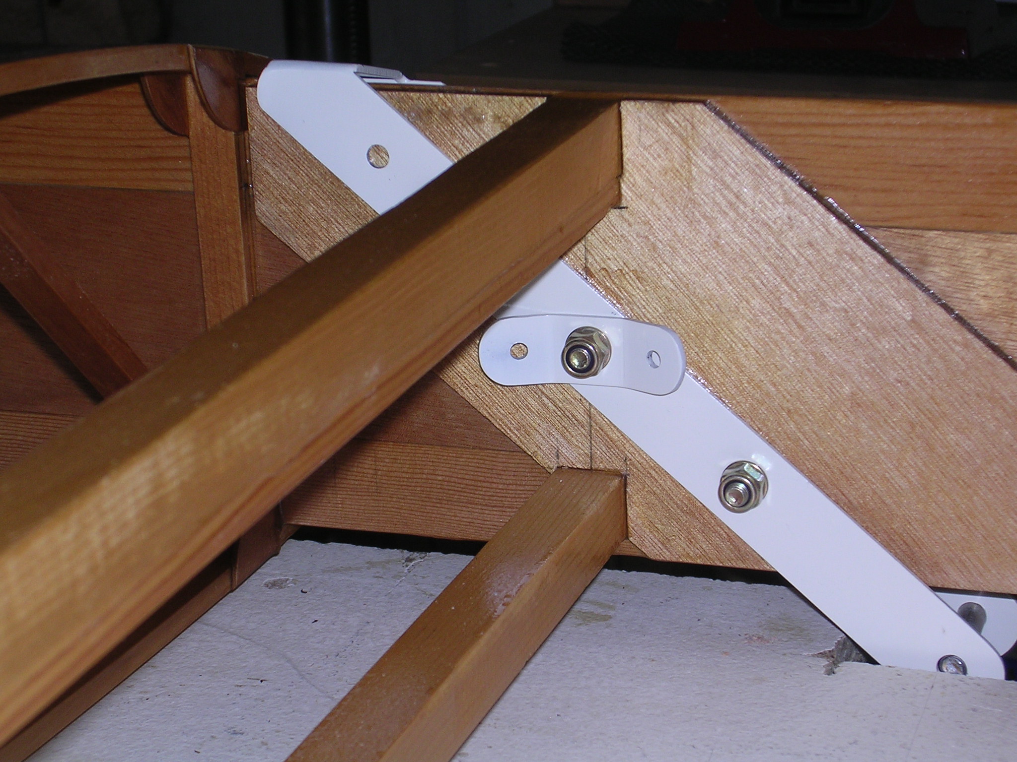
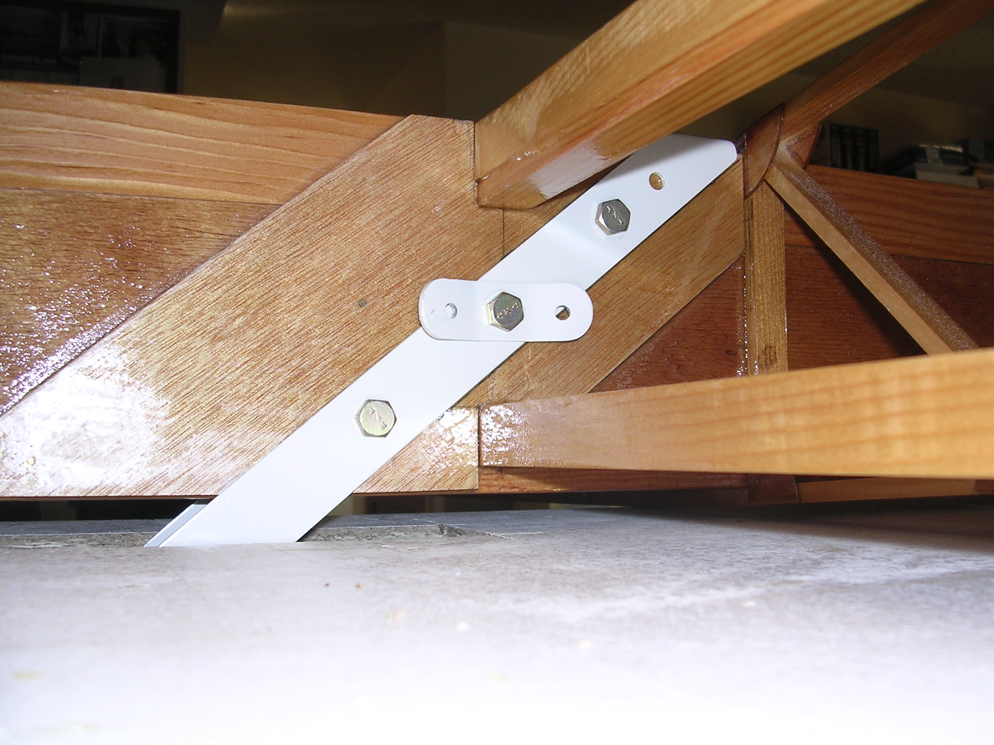
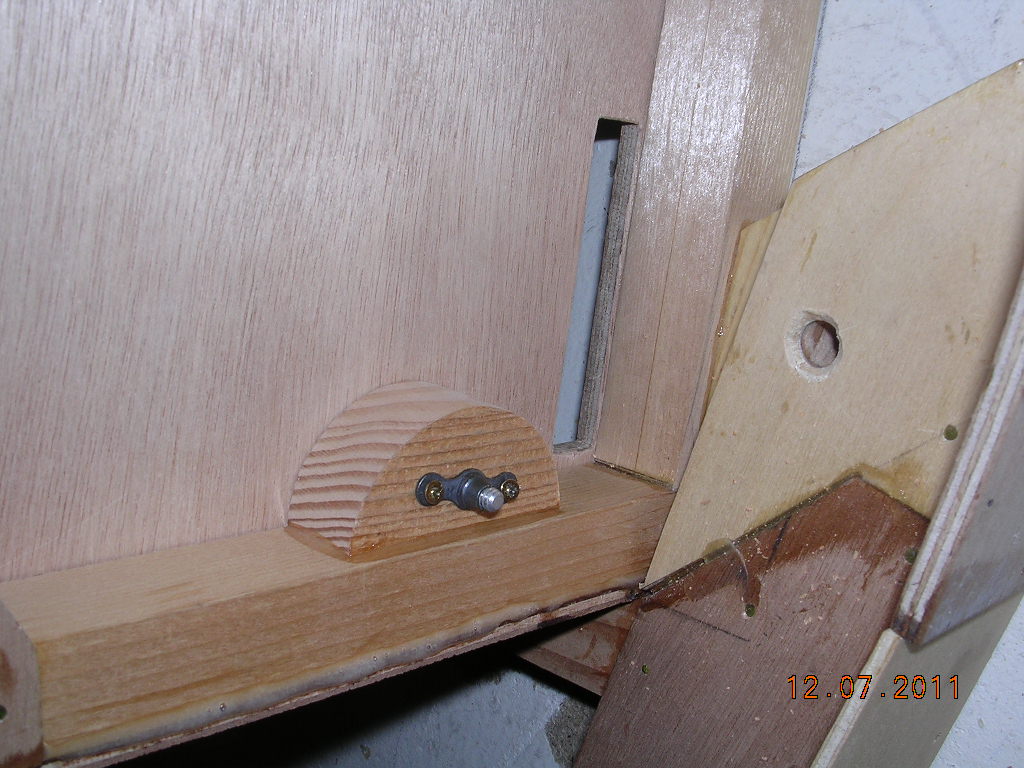
R-seat lap belt point |
Left side belt hard pt |
 |
 |
 |
 |
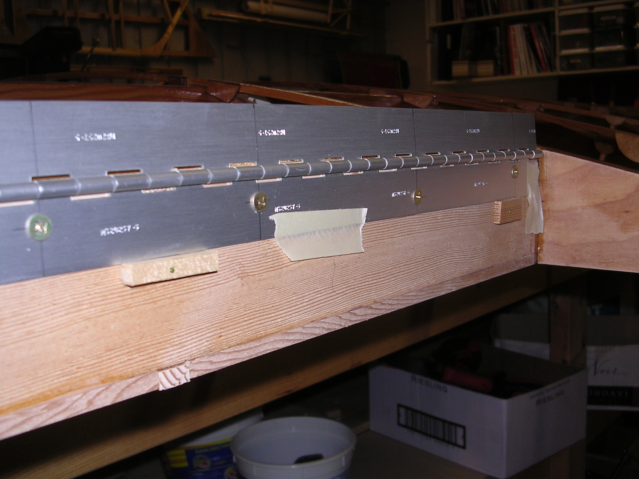
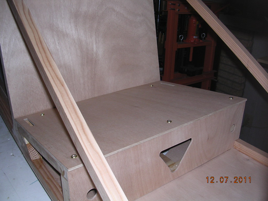
| Access panels cuts |
Gluing backstops |
1" panel compartment extension |
1" extra allows long electric turn & bank |
 |
 |
 |
 |
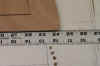
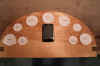
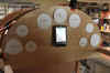
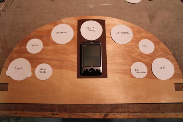
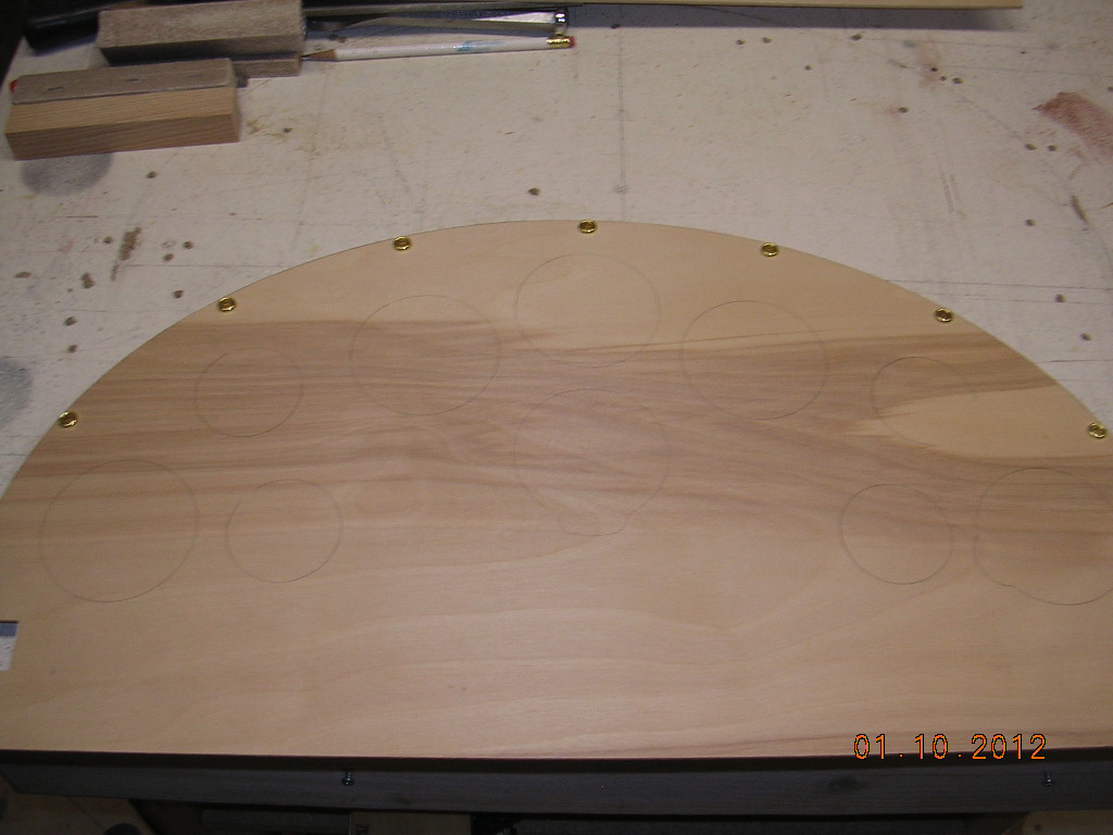
| 1 of a 100 layouts |
1/16th bit for straight cut and knife for curve |
24 1/4 wide |
Trial fitting |
 |
 |
 |
 |
 |
 |
 |
 |
| Very little glued at this point |
|
|
|
|
 |
 |
 |
 |
|
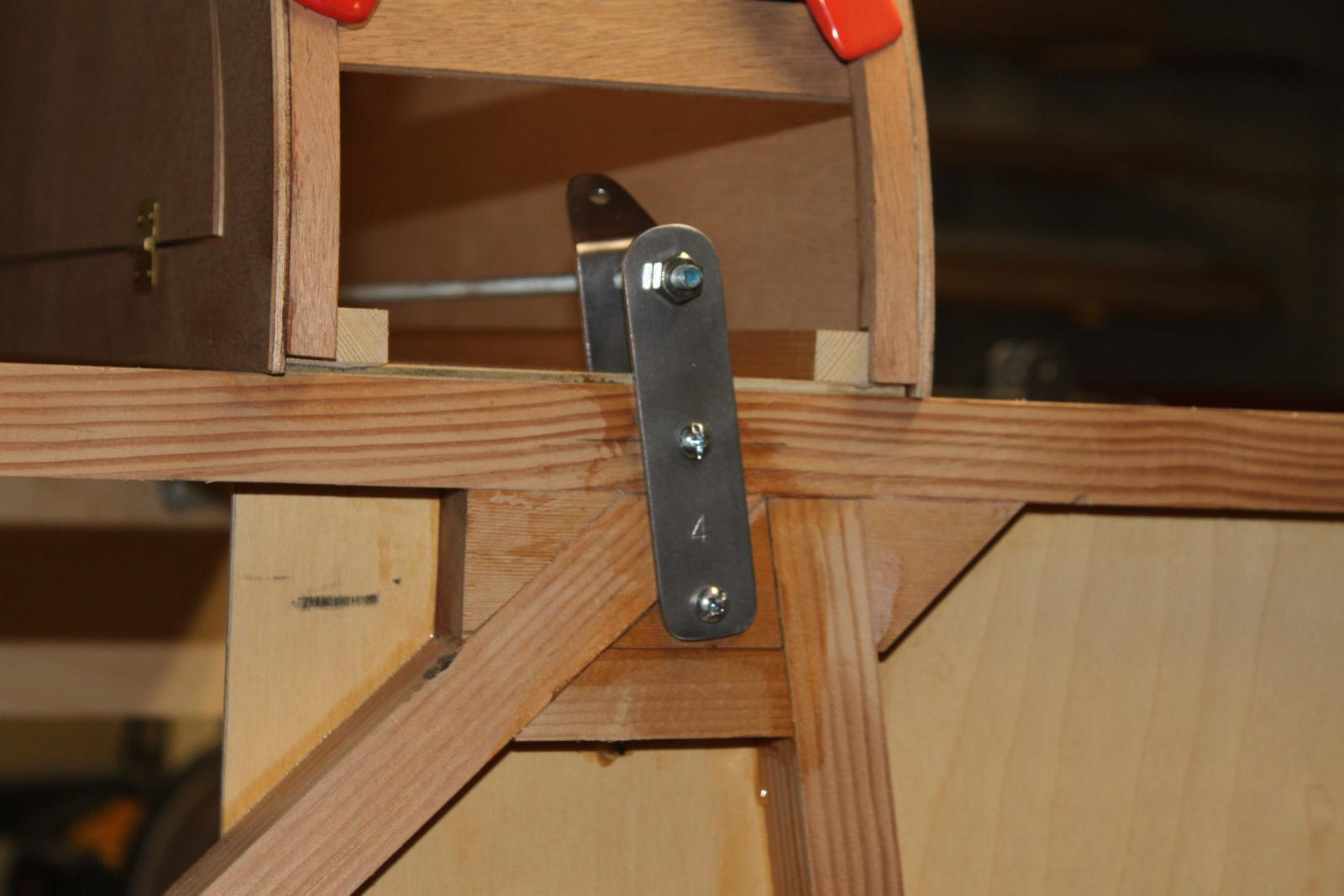
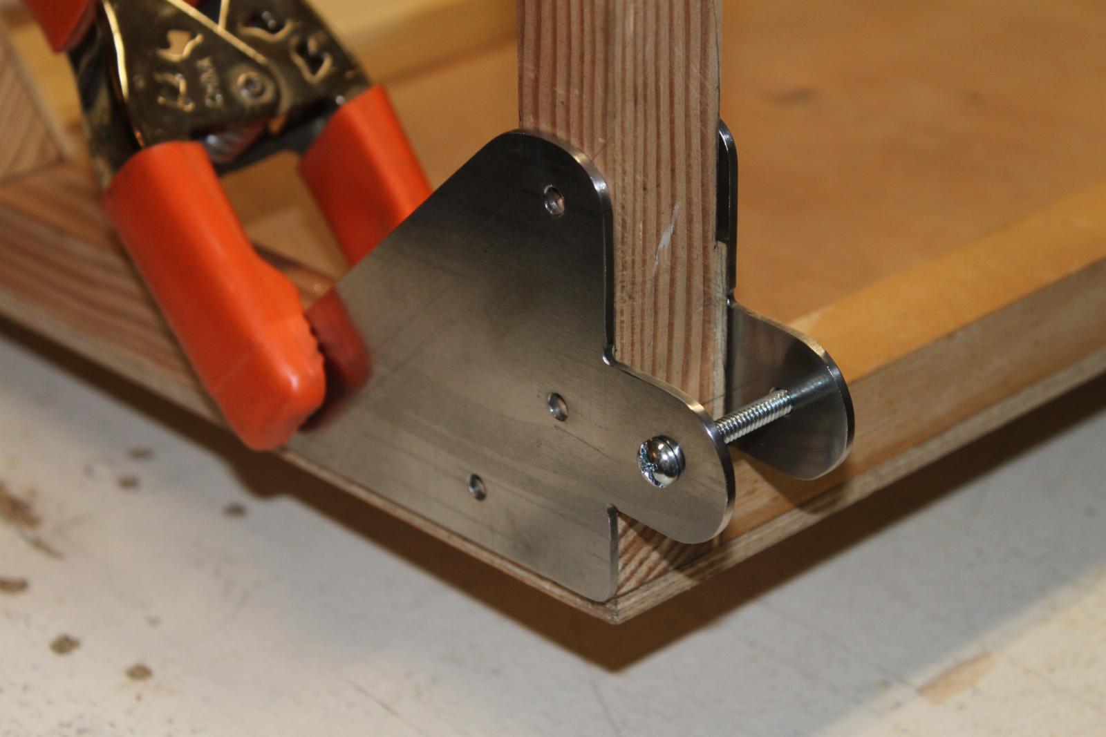
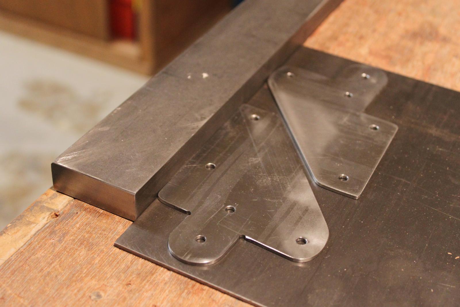
Gluing cowl supports |
Drill jig for strut fittings |
|
|
|
|
|
|
|
|
|
|
|
|
|
|
|
|
|
 |
 |
 |
|
 |
 |
 |
 |
 |
 |
 |
 |
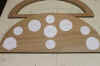
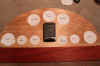
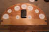
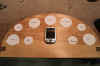
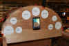
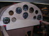
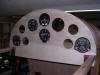
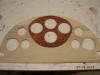
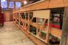
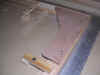
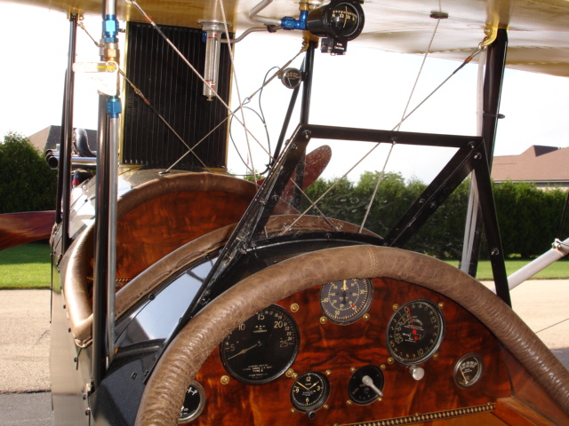
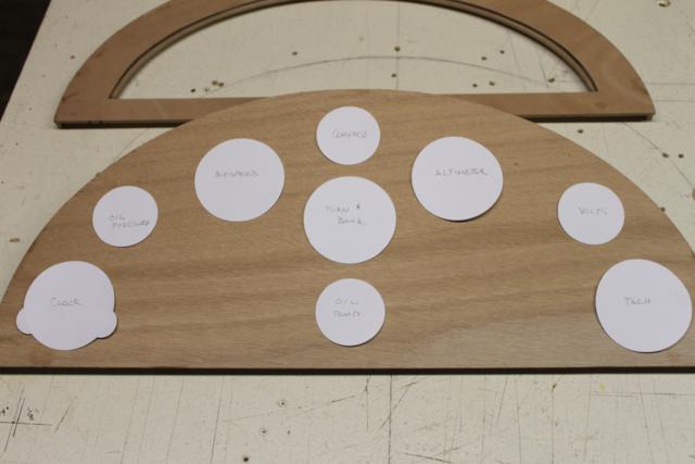
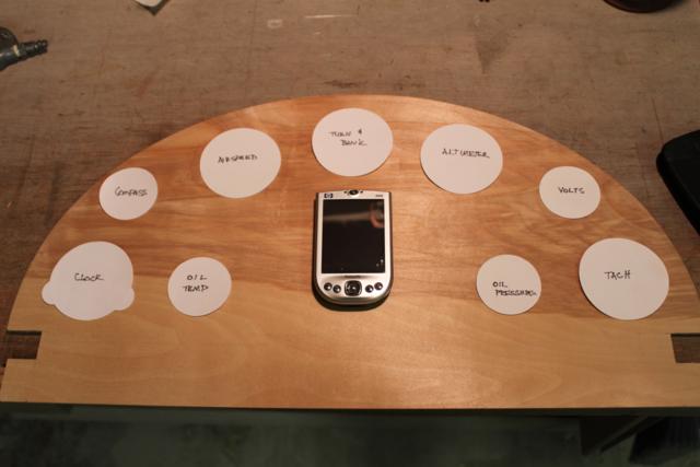
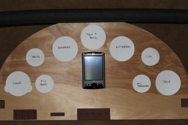
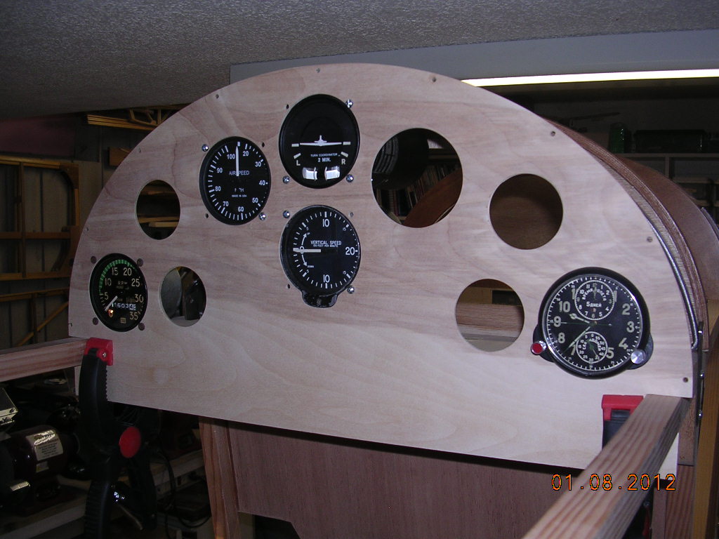
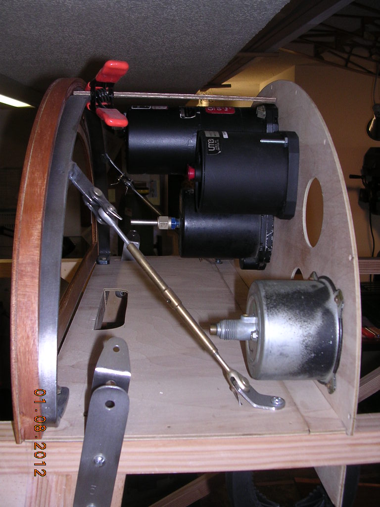
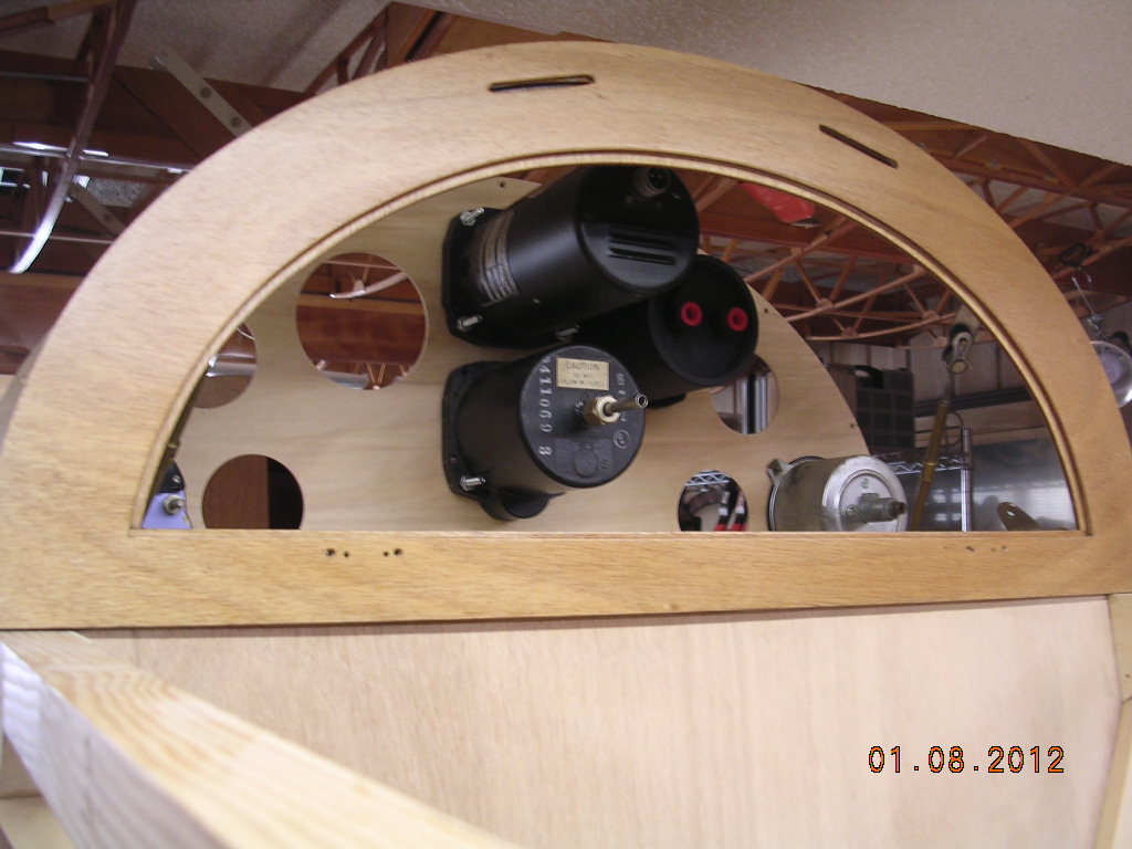
| Way too many choices for panel
layouts! Which will win? |
 |
 |
 |
 |
|
 |
|
|
|
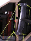
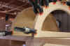
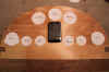
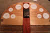
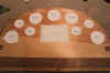
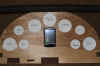
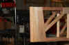
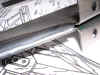
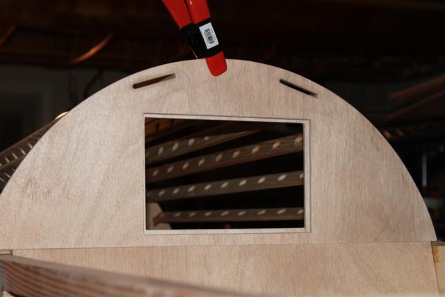
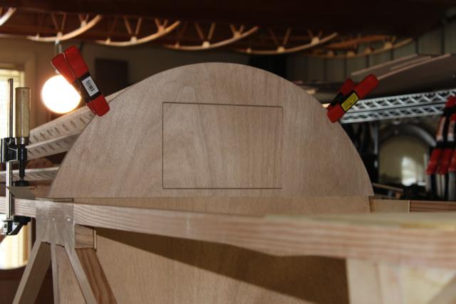
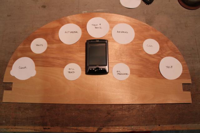
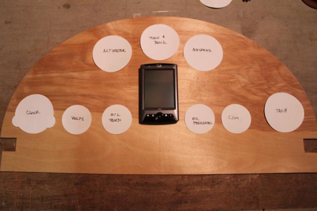
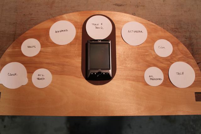
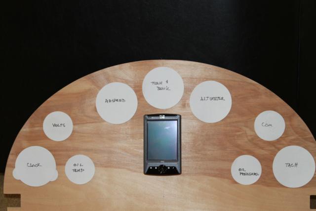
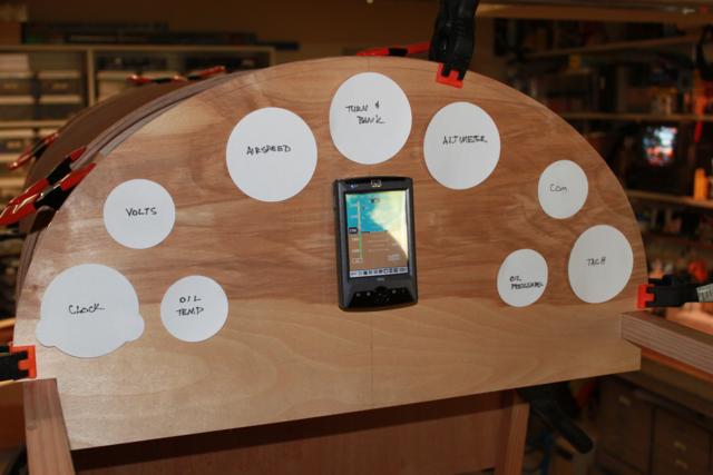
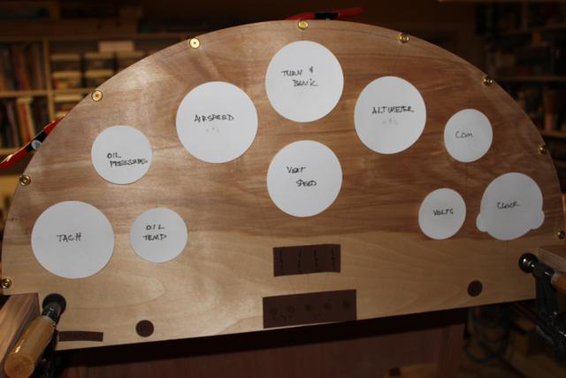
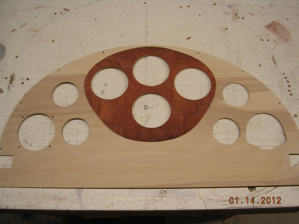
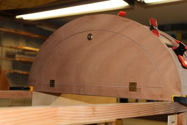
| Winner! I think...compass will be
in center section, GPS on top of cowl behind windscreen.
Faint diagonal lines depict aileron cables behind panel. |
 |
 |
 |
 |
| |
|
|
Plan to re-cut |
 |
 |
 |
 |
| |
|
Too close |
|
 |
|
|
|
| May do overlay |
|
|
|
| |
|
|
|
 |
 |
 |
 |
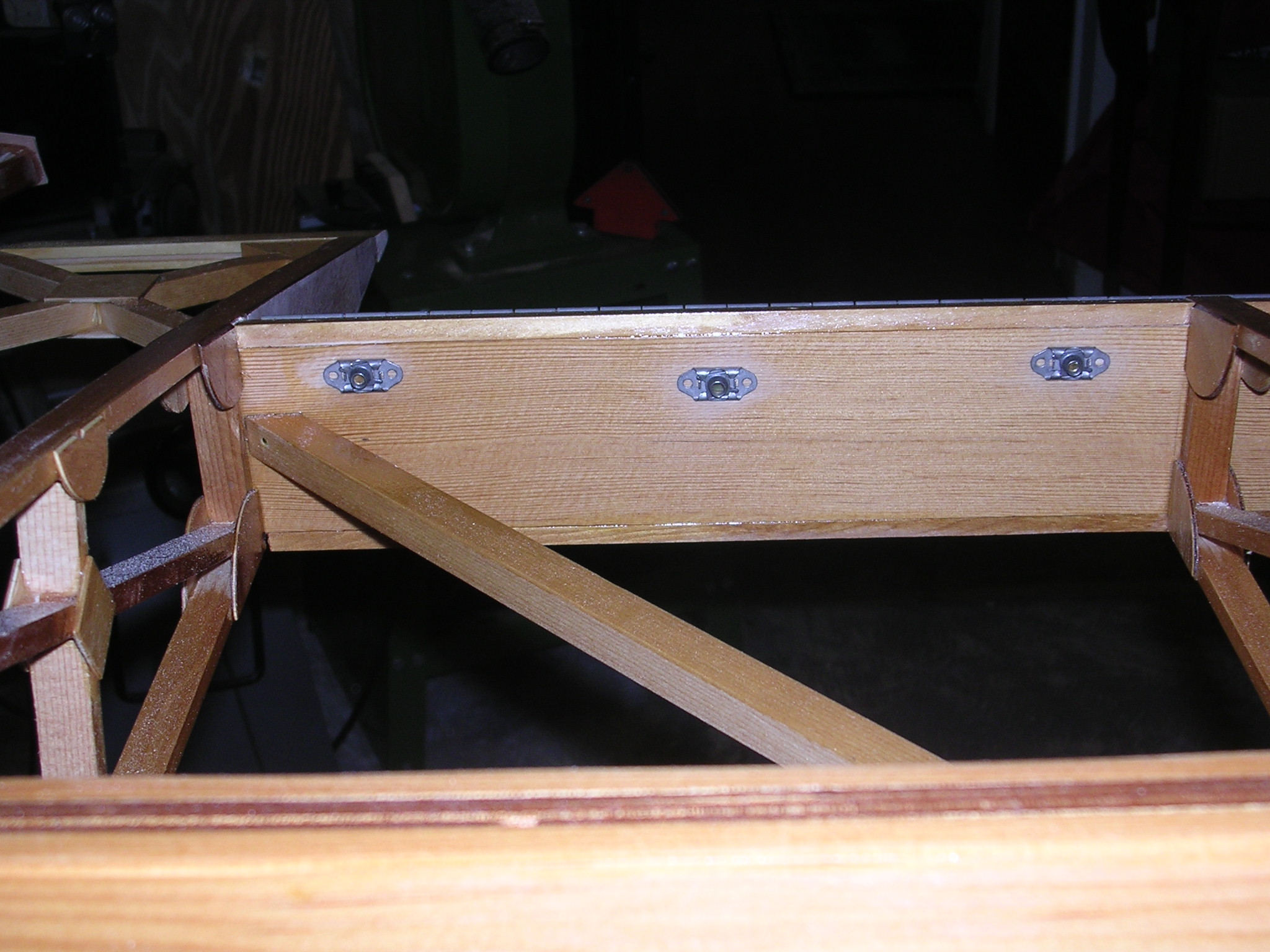
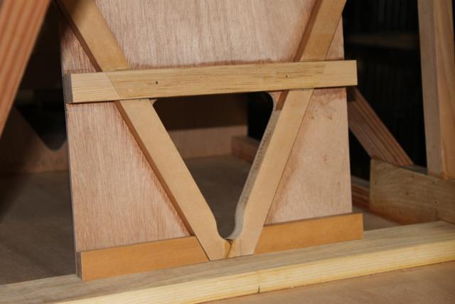
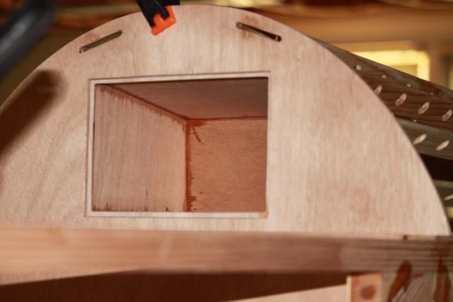
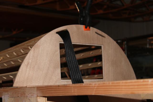
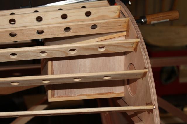
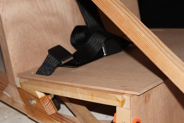
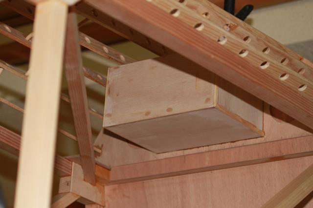
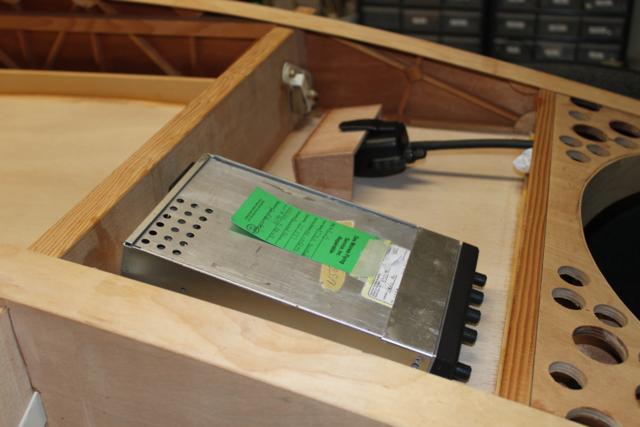
| Using the right box |
Cutout w/razor knife |
Belt clears box |
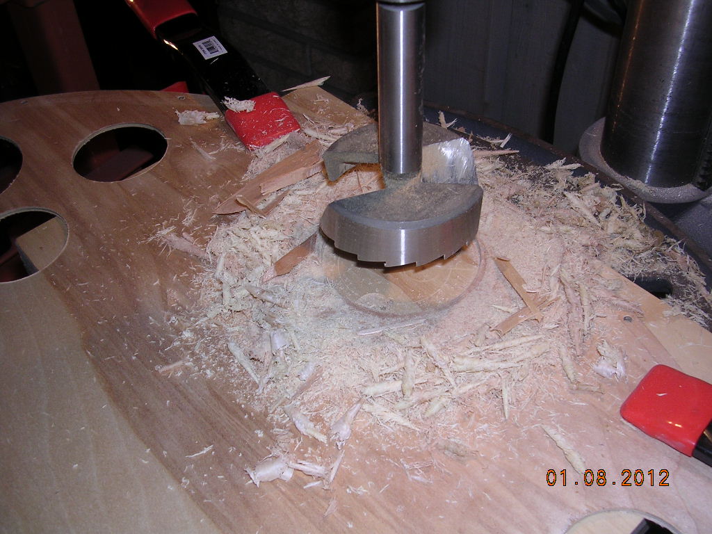
Instrument access |
 |
 |
 |
 |
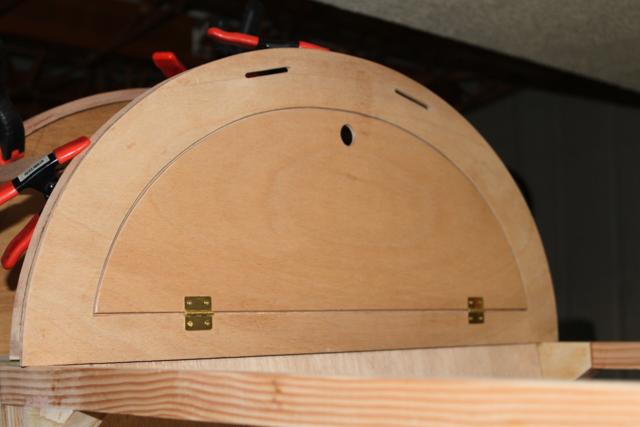
| Lockable |
|
|
|
 |
 |
 |
|
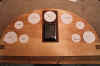
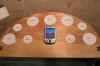
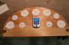
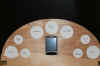
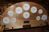
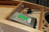
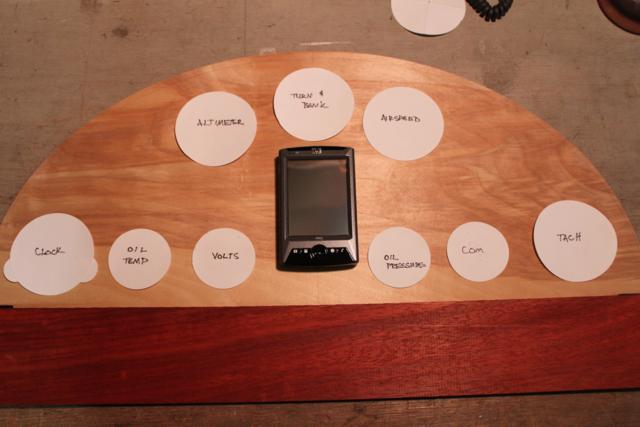
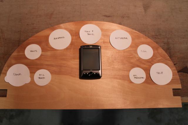
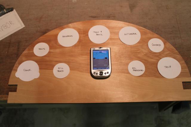
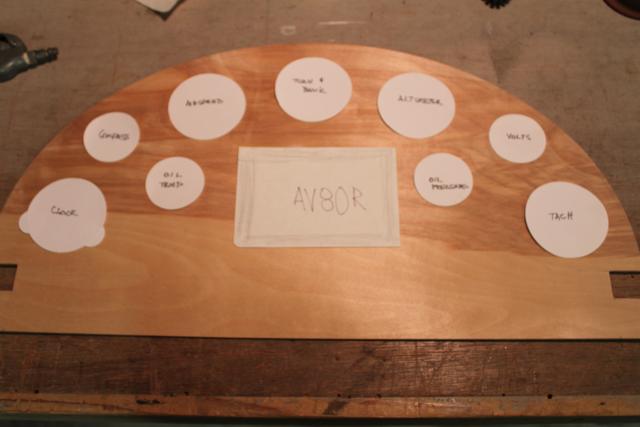
| More trials, not sure on portable nav/com,
will use transponder |
|
|
|
|
|
|
|
|
 |
 |
 |
 |
 |
 |
 |
 |
 |
 |
 |
 |
 |
 |
 |
 |
 |
 |
 |
 |
 |
 |
 |
 |
 |
 |
 |
 |
|
|
Don't install wedge here as I did |
|
 |
 |
 |
 |
 |
 |
 |
 |
 |
 |
 |
 |
 |
 |
 |
 |
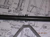
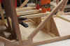
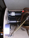
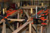
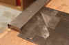
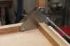
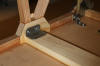
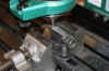
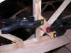
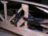
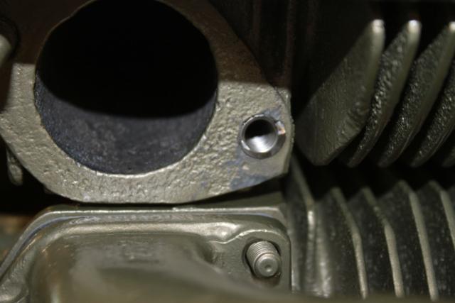
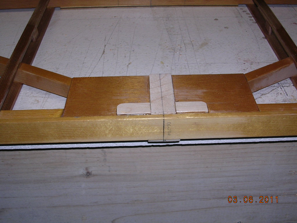
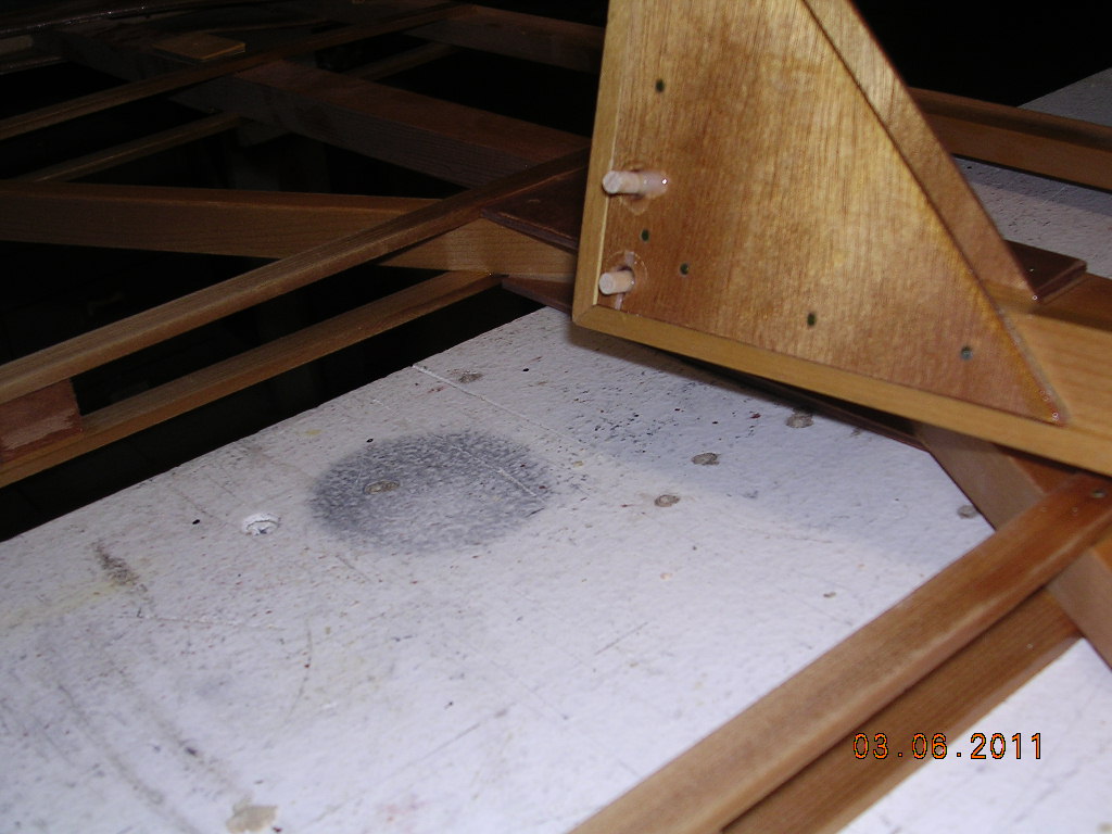
| 2nd & 3rd pics-cutting out block in
the way of lower engine mounts. I elected to NOT cut |
| lower cross piece to make way for
mount. Altered mounts raising mount 1/2" |
 |
 |
 |
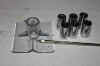 |
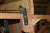
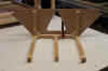
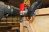
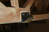
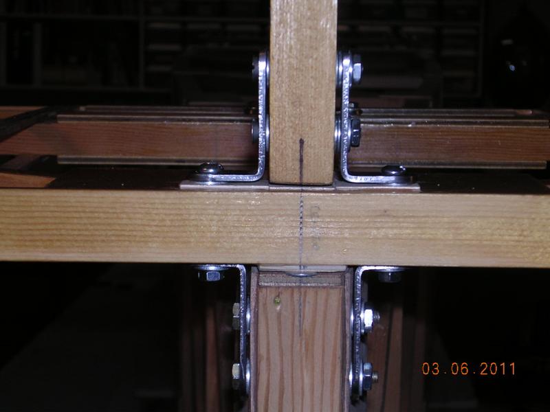
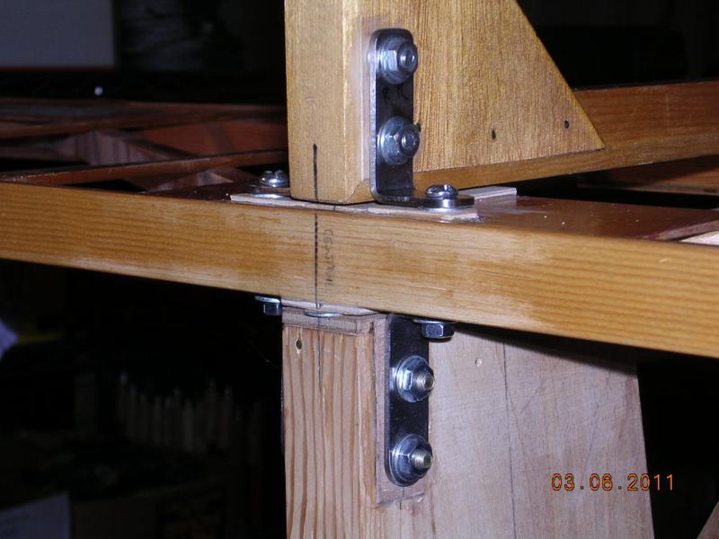
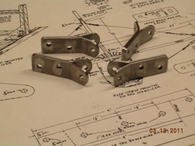
| Upper mount |
Lowers mounts |
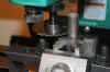
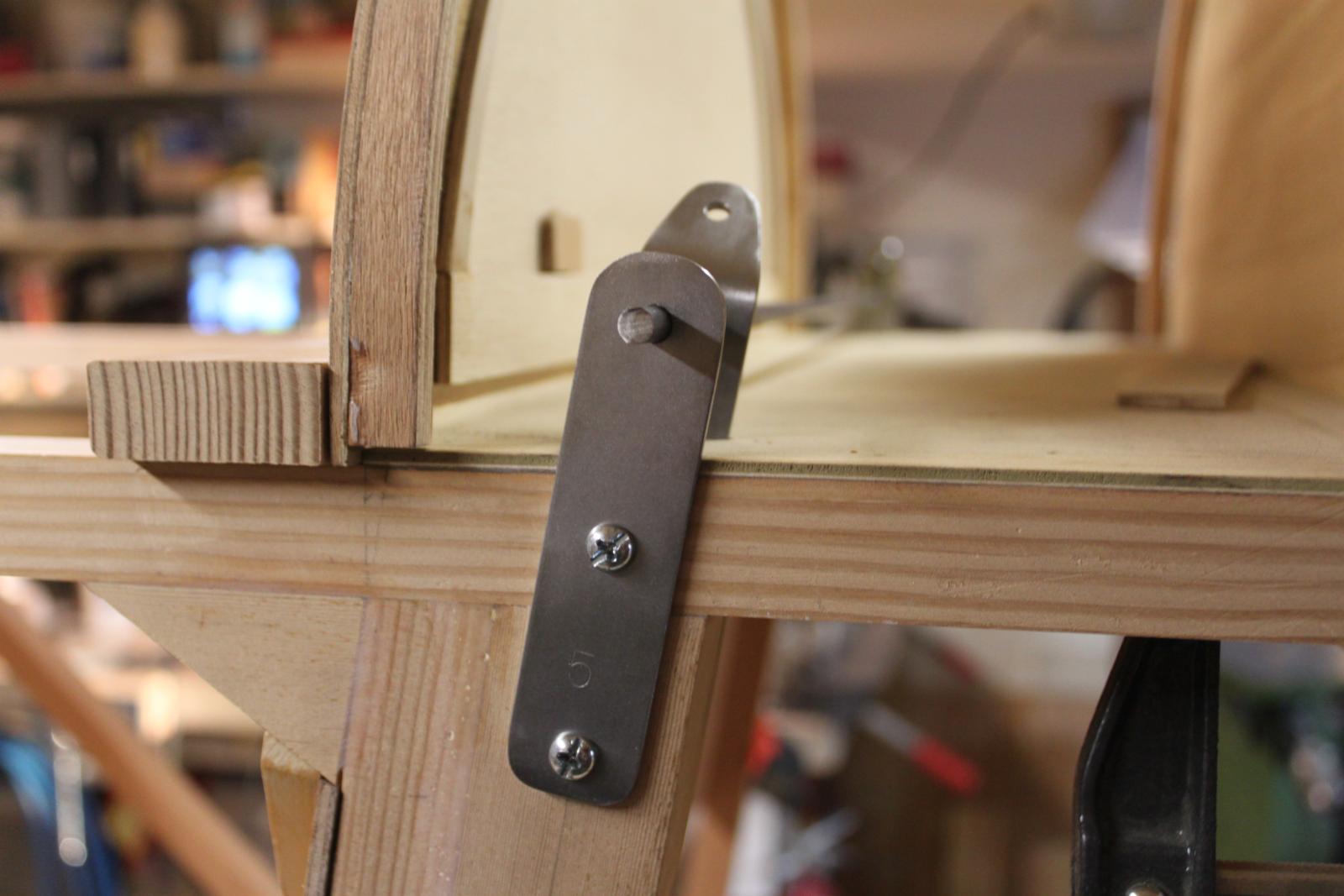
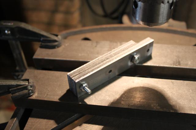
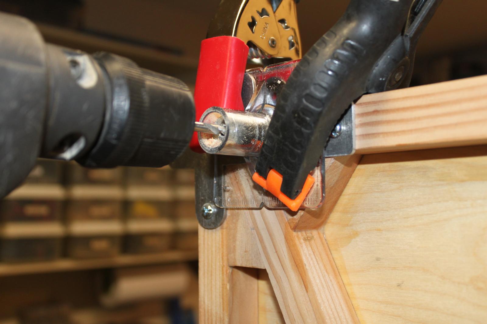
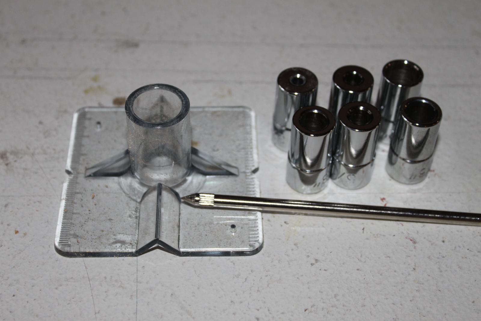
A big help for boring perfect holes, it
works! |
 |
 |
 |
 |
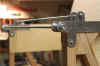
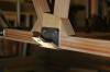
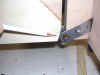
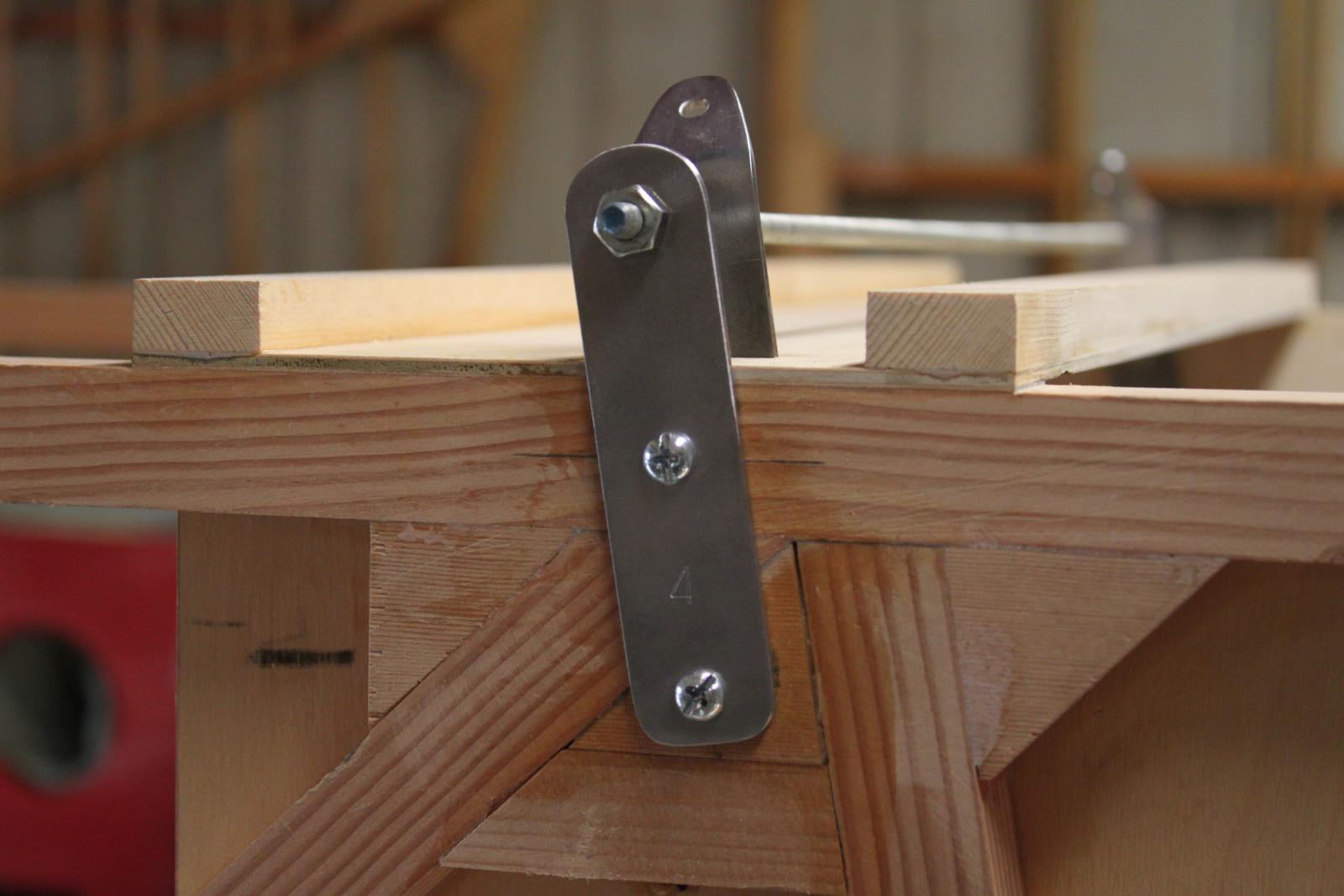
| Mounts aligned and drilled, all fittings
and holes matched very well, a good day! |
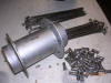
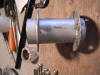
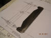
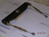
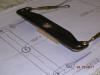
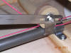
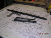
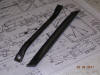
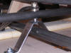
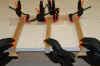
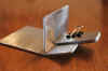
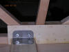
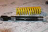
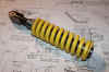
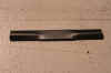
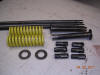
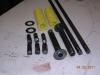
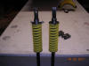
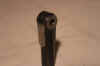
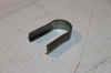
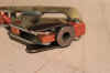
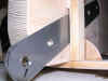
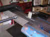
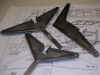
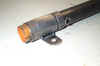
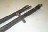
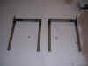
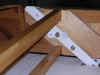
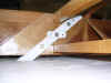
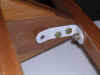
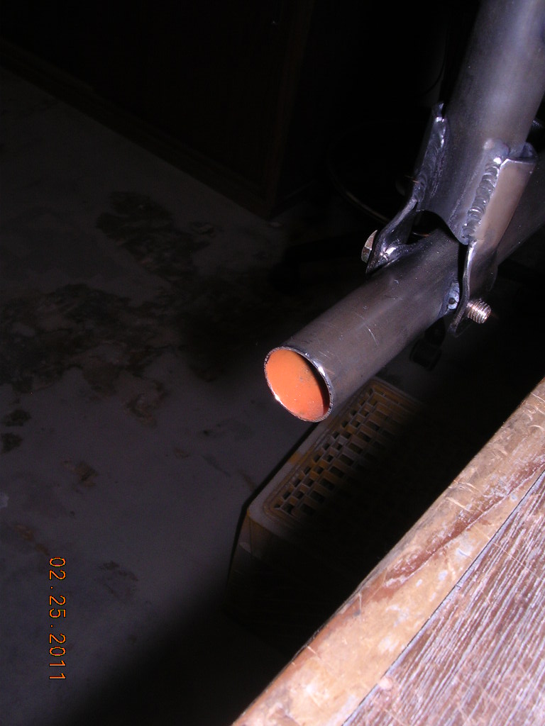
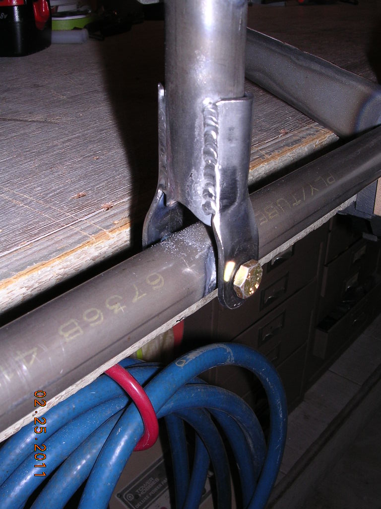
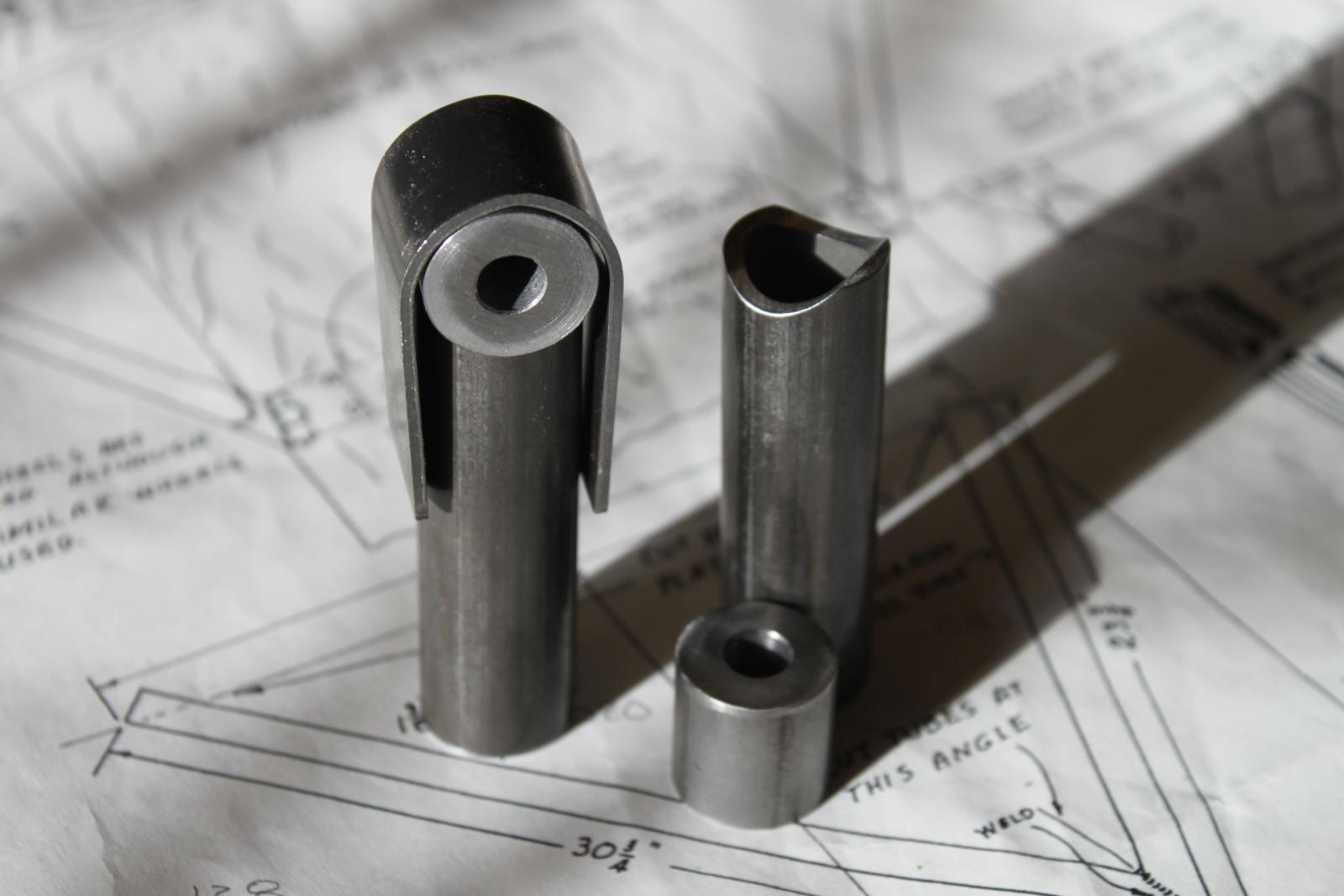
| CONSTRUCTION PHOTOS (Gear) |
 |
 |
 |
|
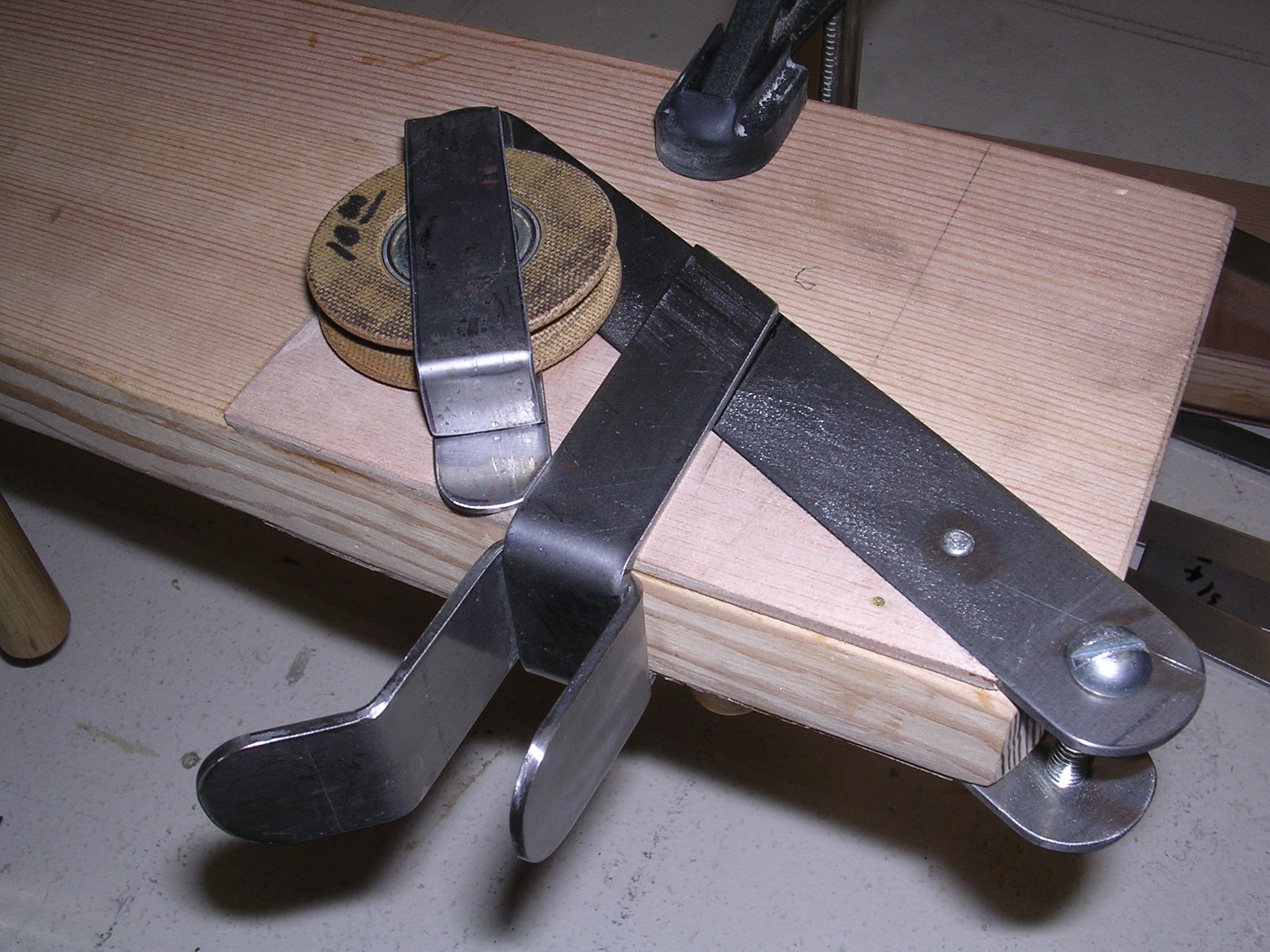
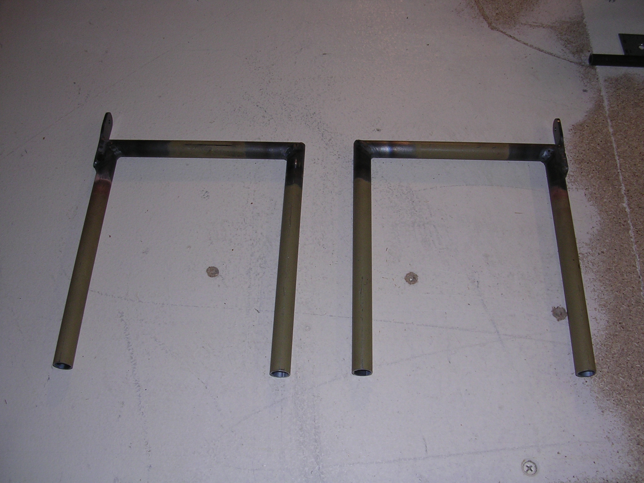
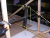
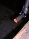
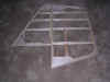
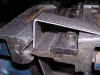
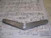
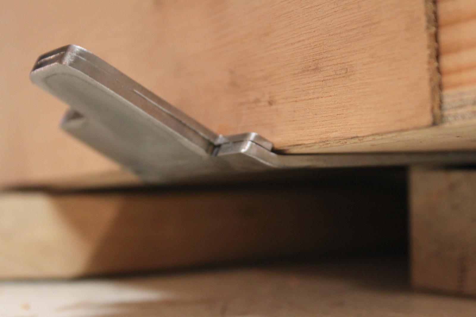
| Gear fitting, 110 degree bend, still
cracked, may re-design with 3 pieces |
|
 |
 |
 |
 |
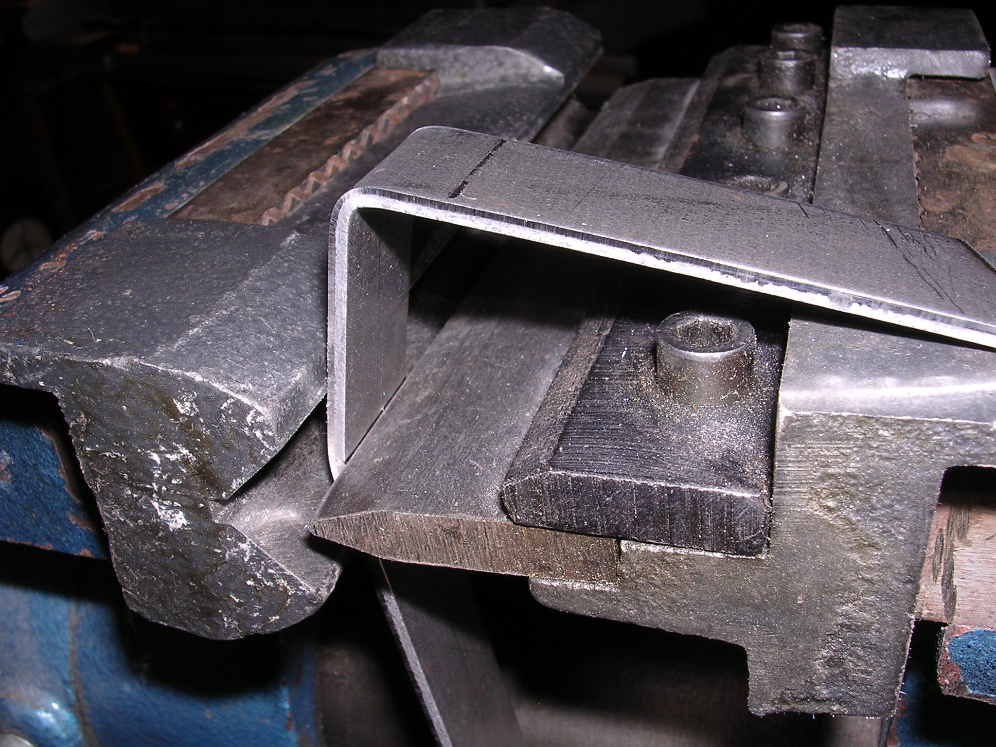
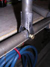
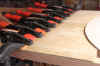
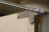
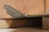
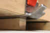
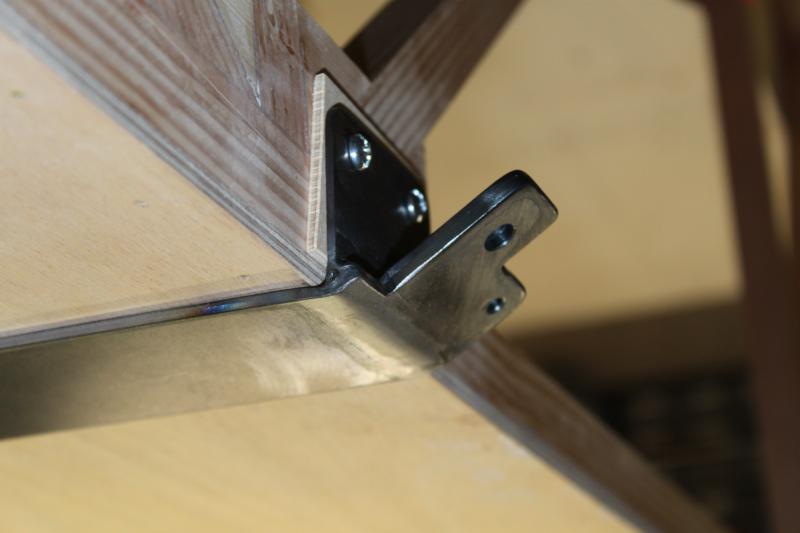
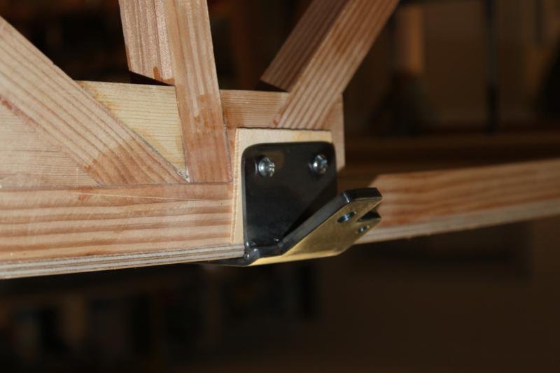
| Went with .130 1018 strap across bottom,
.090 4130 doublers and side plates before welding |
|
|
|
|
|
|
|
|
 |
 |
|
 |
|
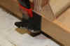
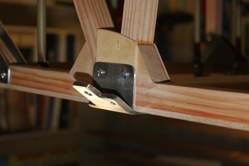
Don't forget
|
1/8" spacer for sides |
|
|
 |
 |
 |
 |
 |
 |
 |
 |
 |
 |
 |
|
 |
 |
 |
 |
 |
 |
 |
 |
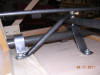
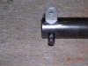
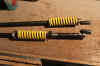
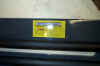
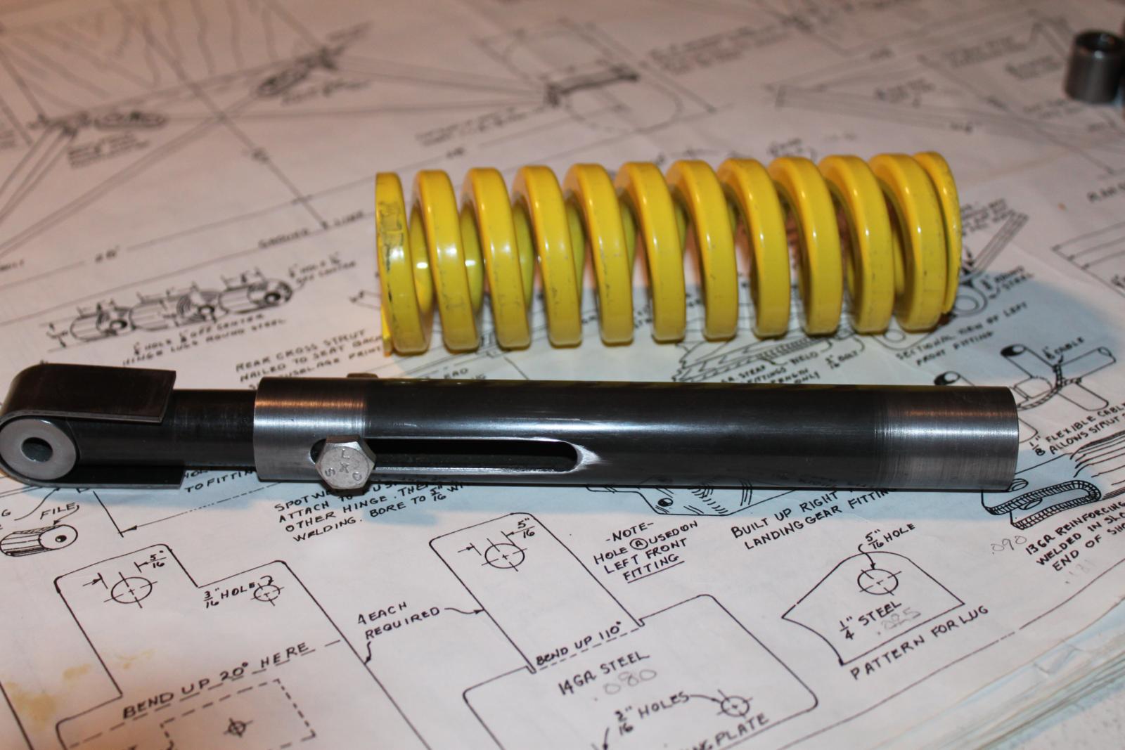
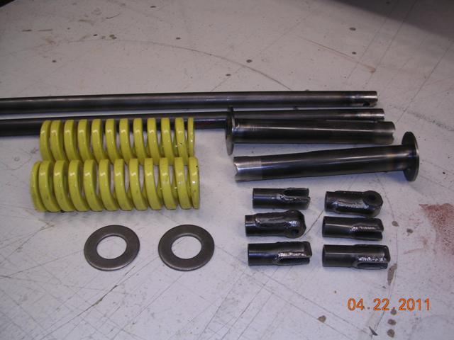
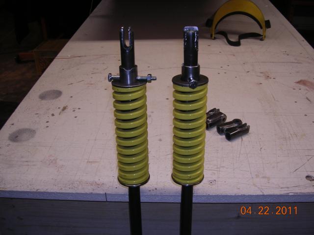
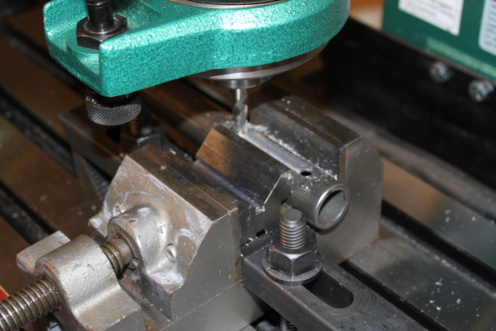
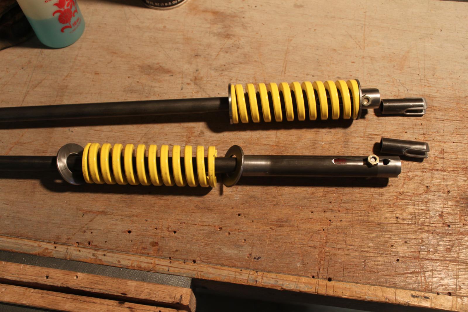
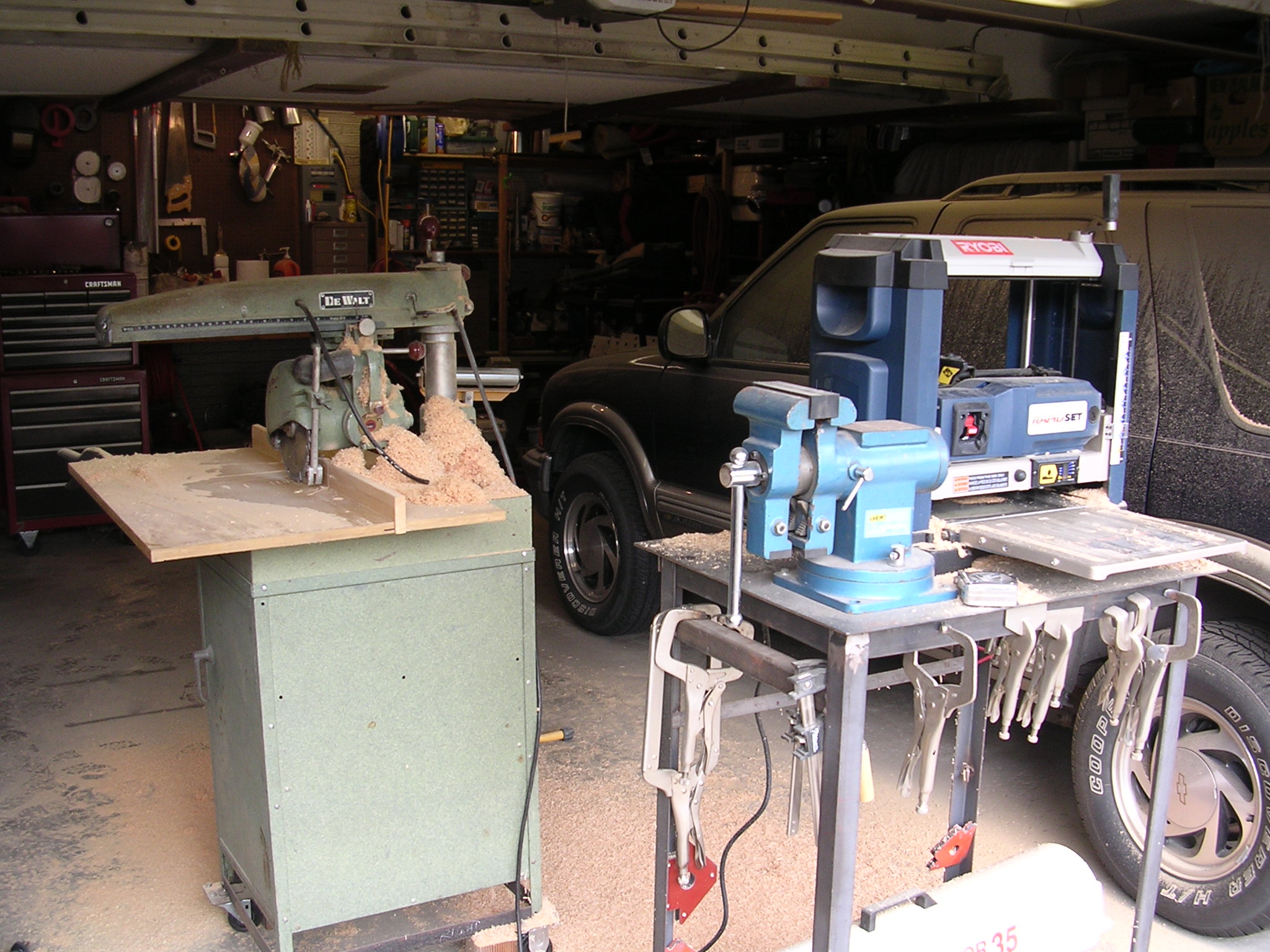
| New Grizzly G1006 |
|
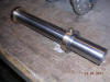
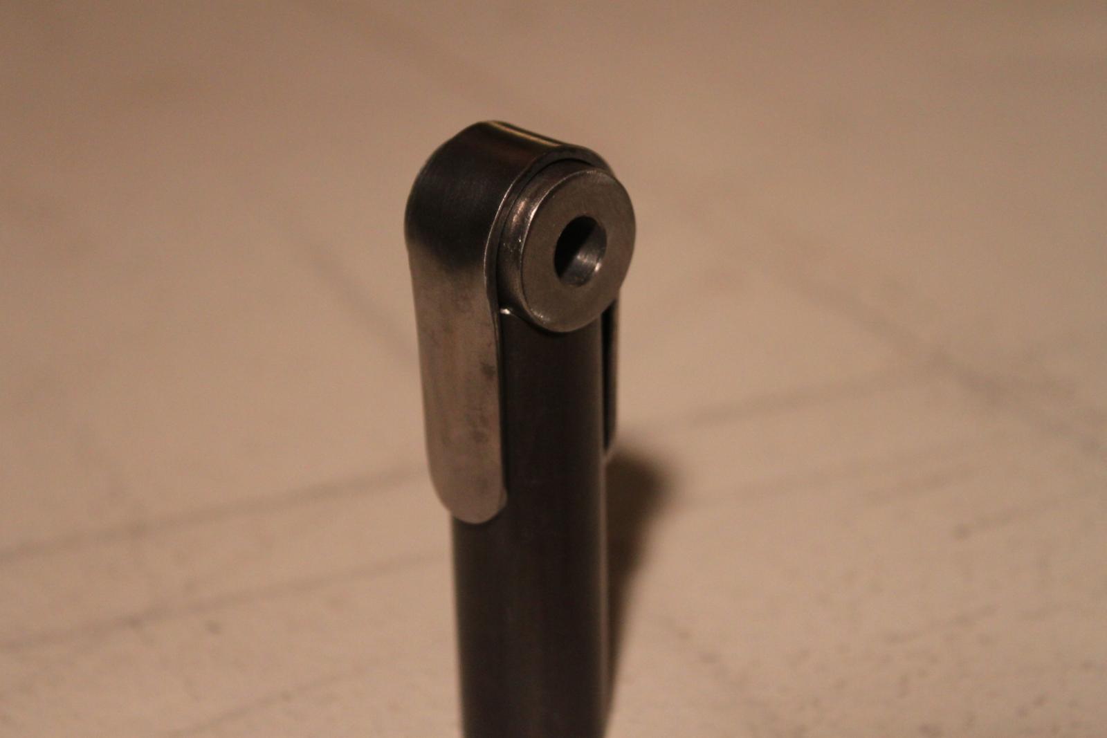
Gear struts |
Female & male ends |
|
|
|
|
|
|
|
|
|
|
|
|
 |
 |
 |
 |
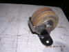
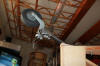
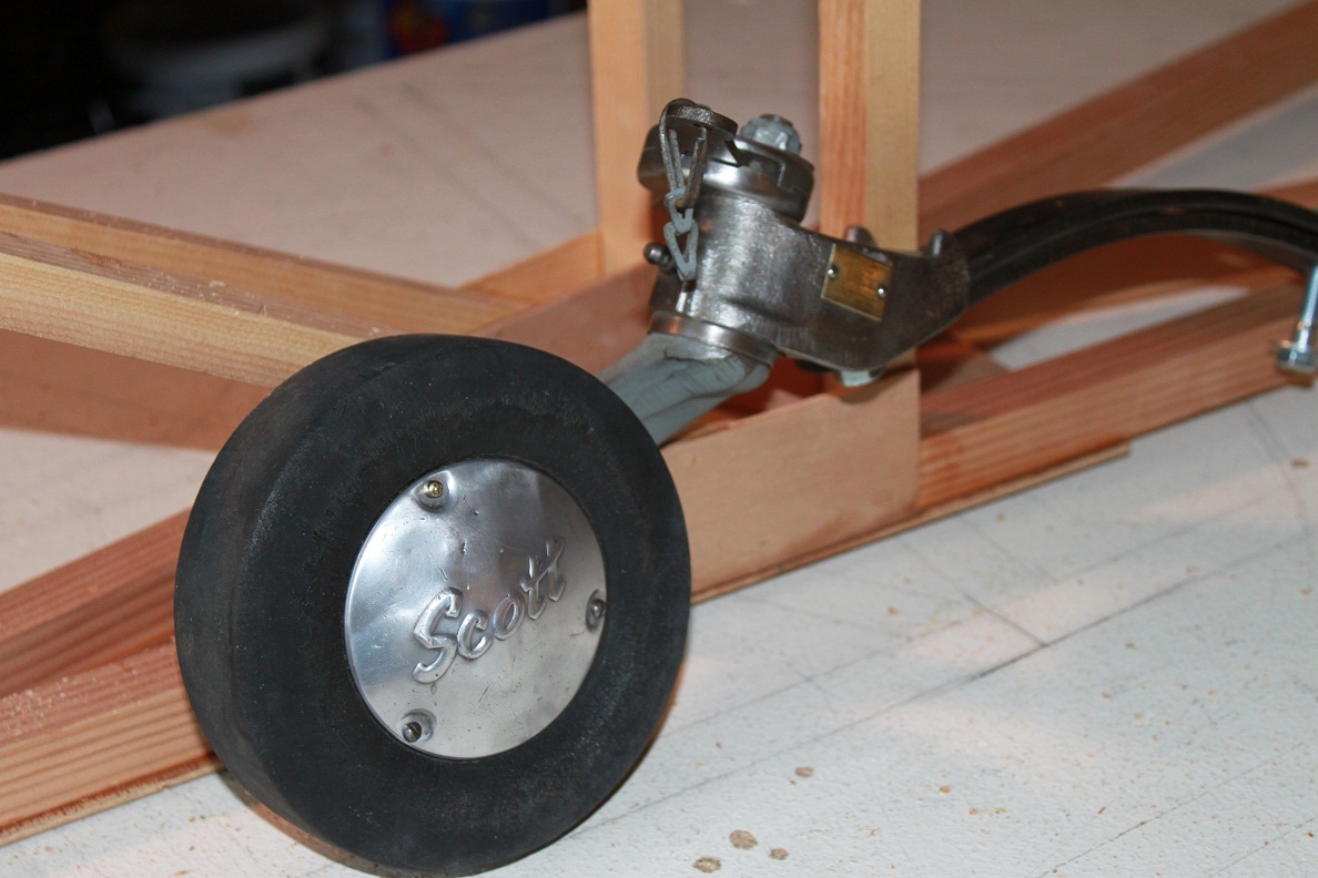
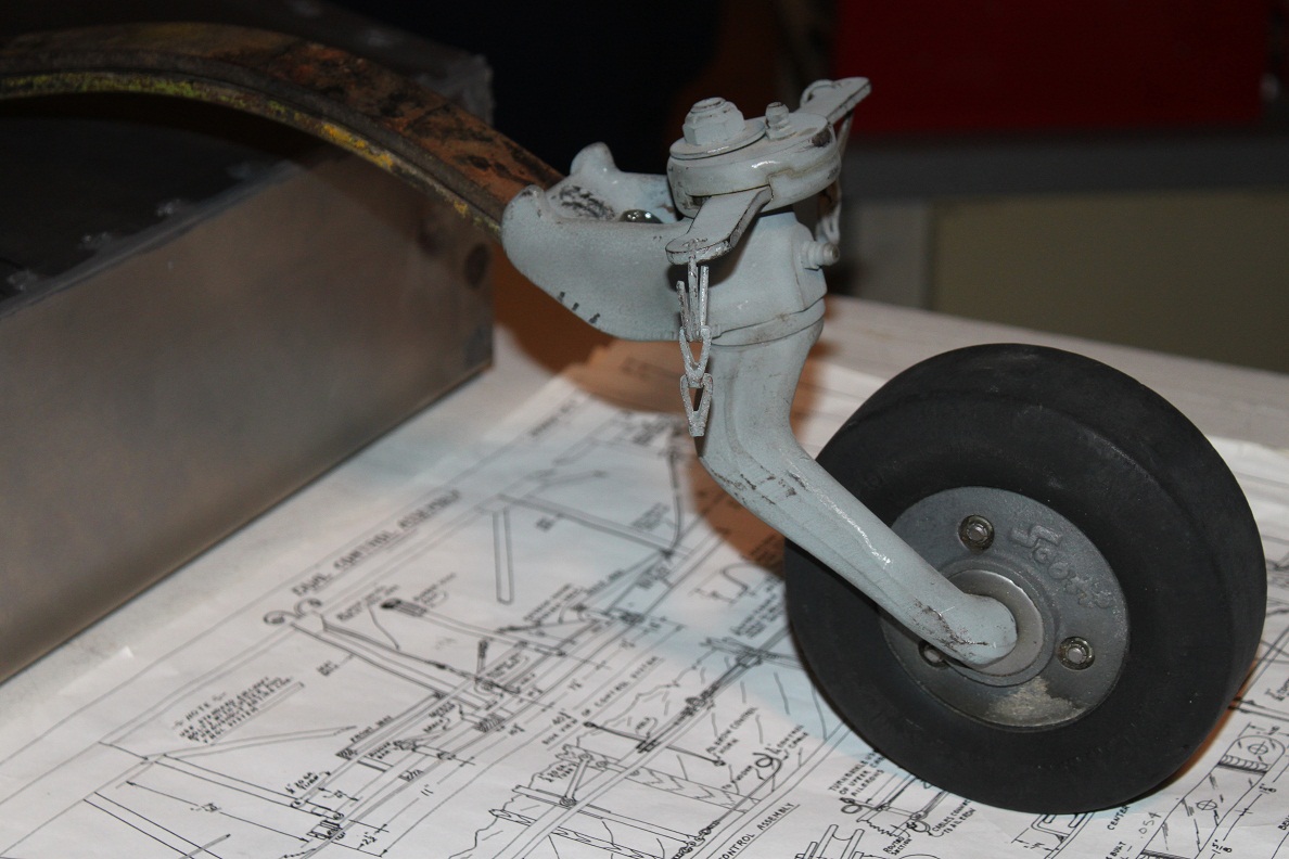
| Scott tail-wheel, 4-1/2 pounds, 6" |
Before clean-up |
 |
 |
 |
 |
| |
|
|
|
| |
|
|
|
 |
 |
 |
 |
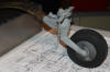
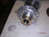
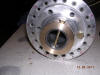
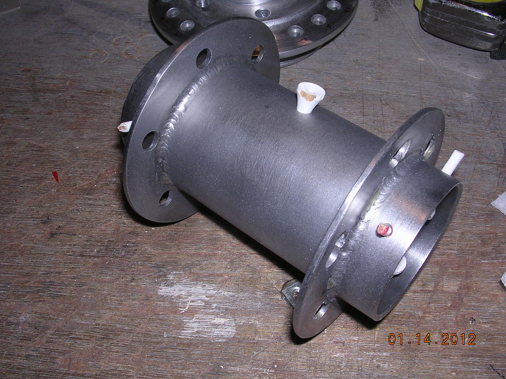
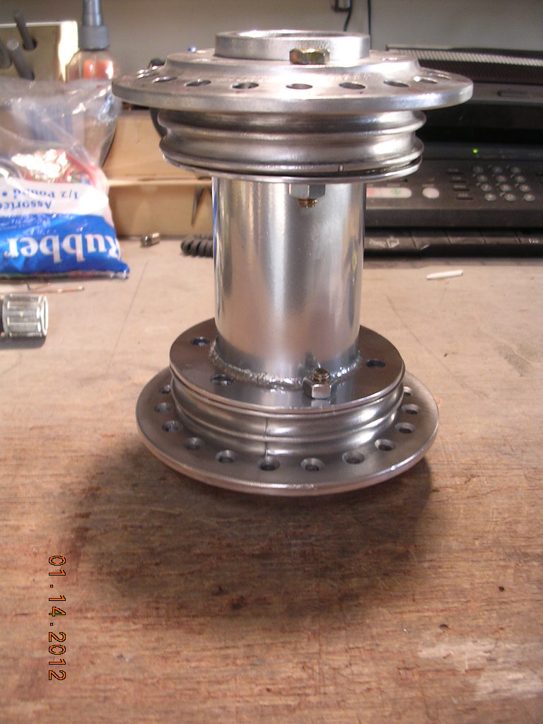
| Before powder coat |
Not happy with purchased hub, plan to
redo, nice powder coat though |
|
|
|
|
| |
|
|
|
| |
|
|
|
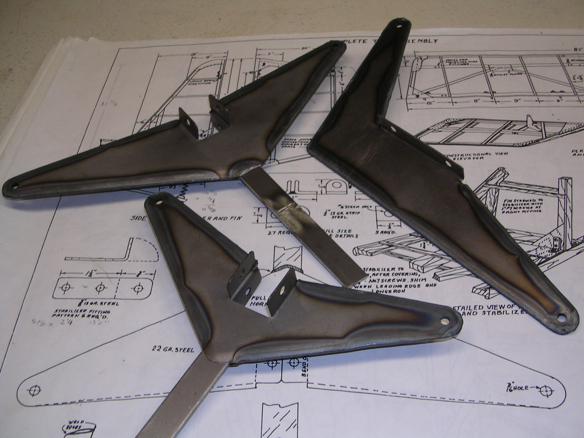
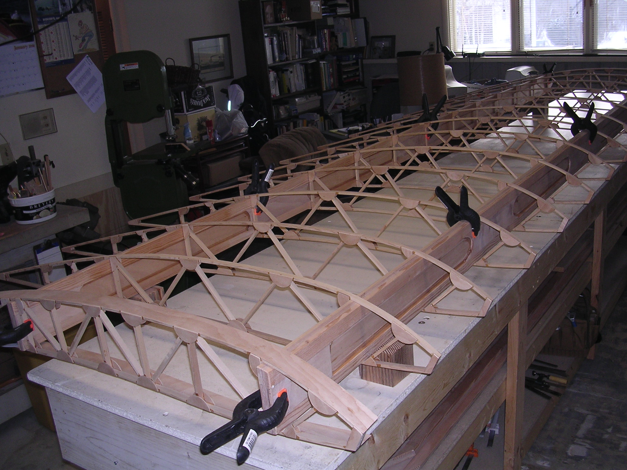
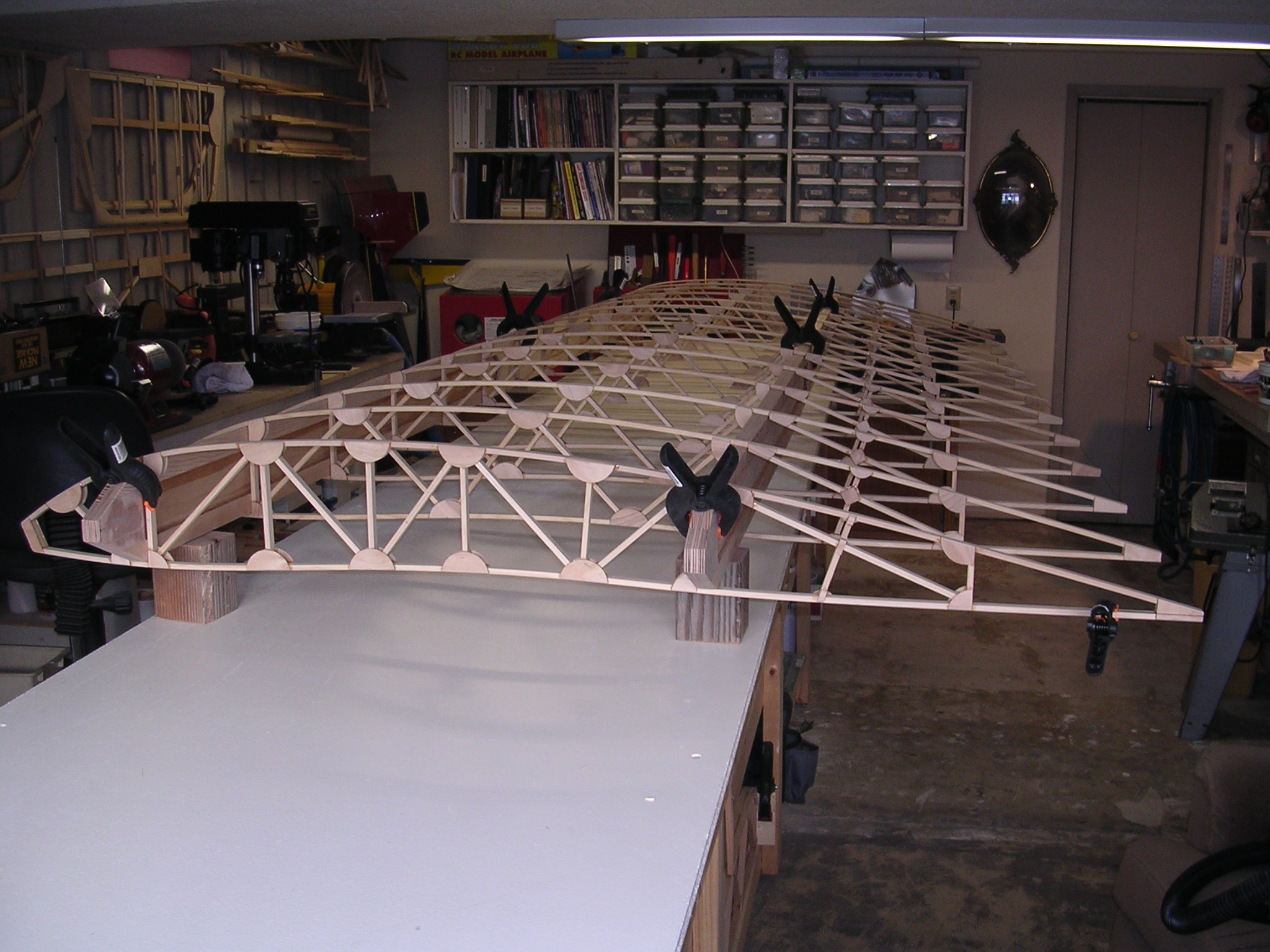
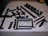
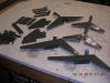
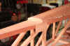
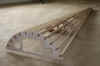
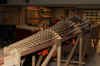
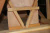
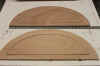
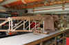
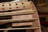
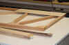
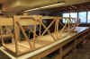
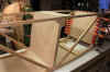
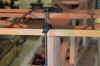
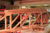
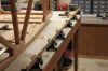
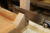
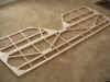
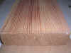
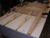
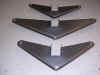
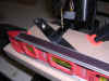
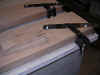
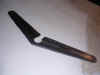
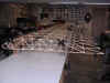
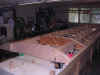
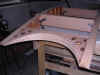
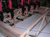
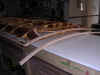
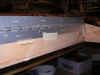
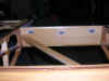
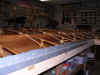
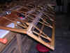
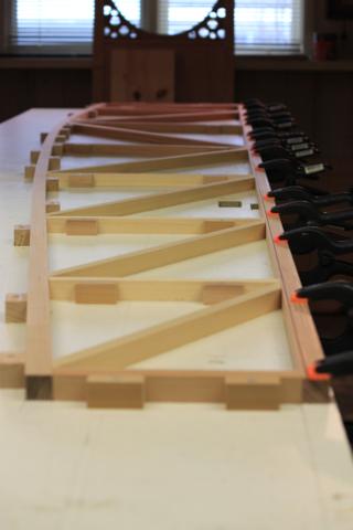
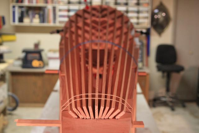
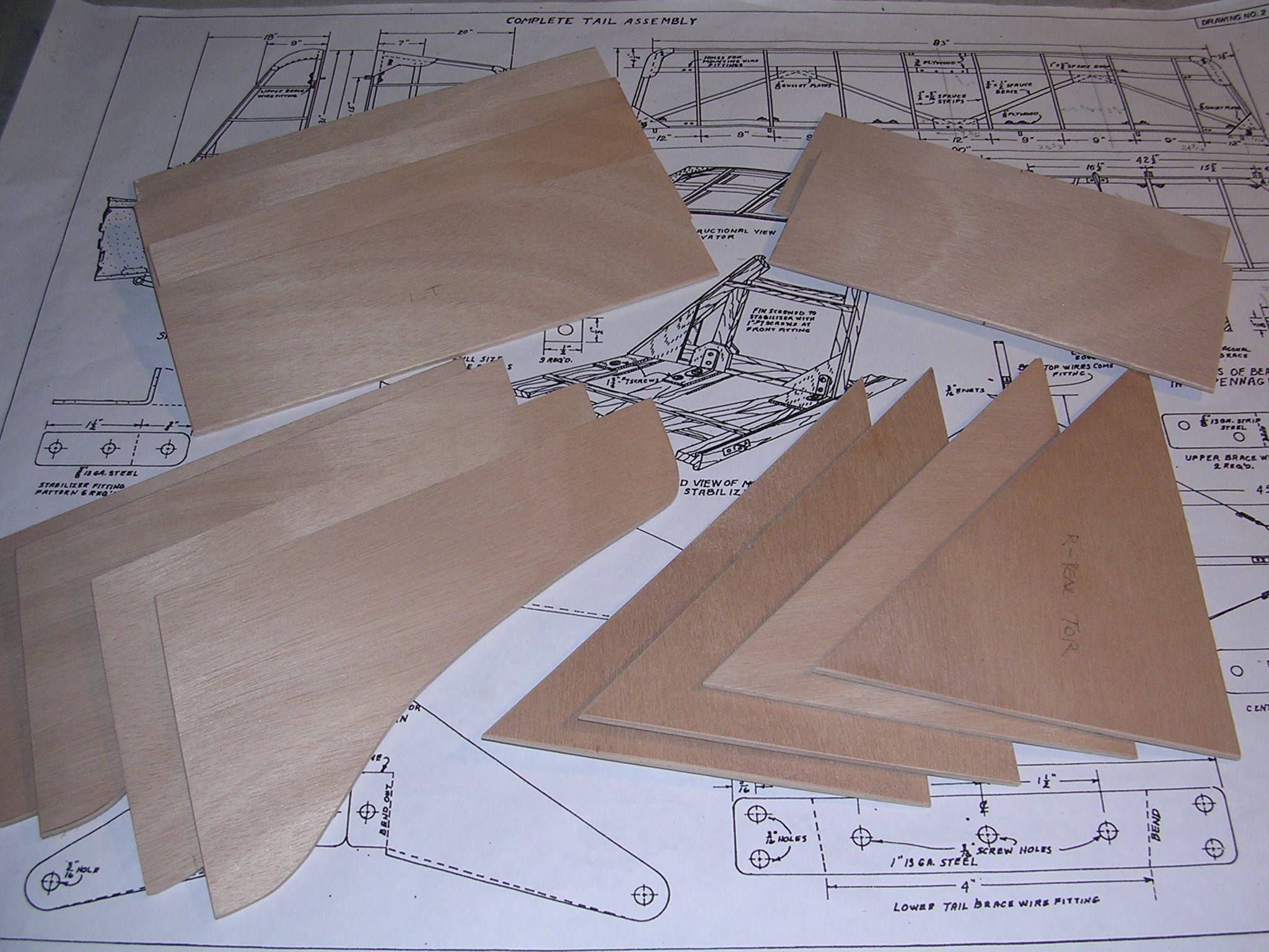
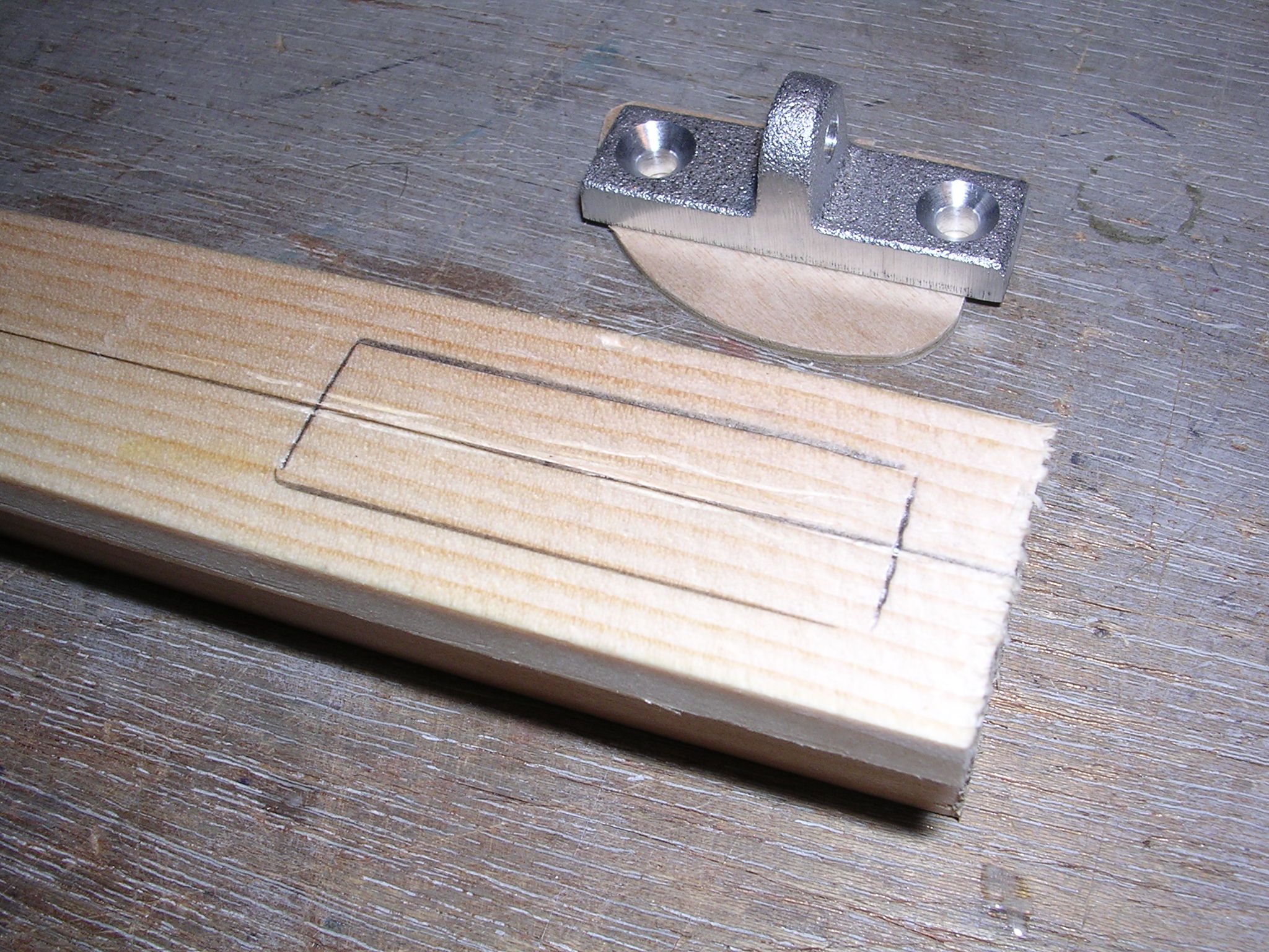
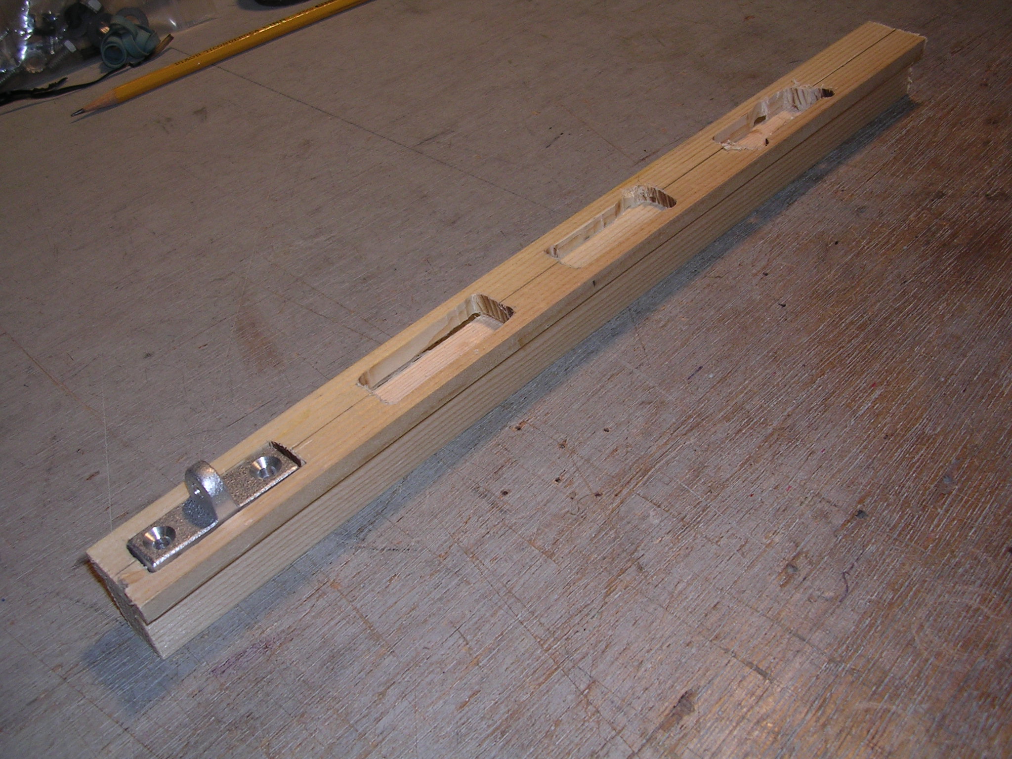
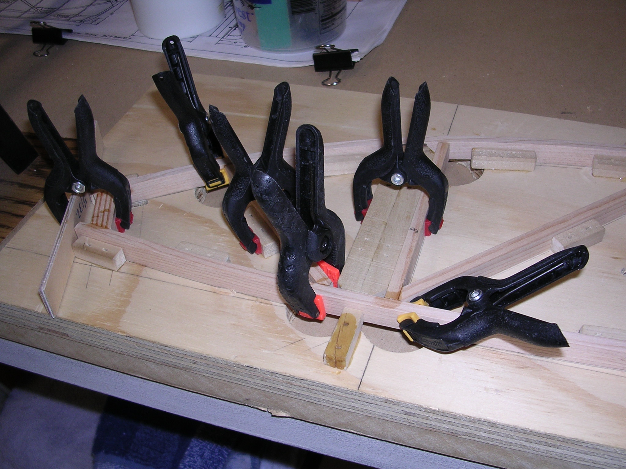
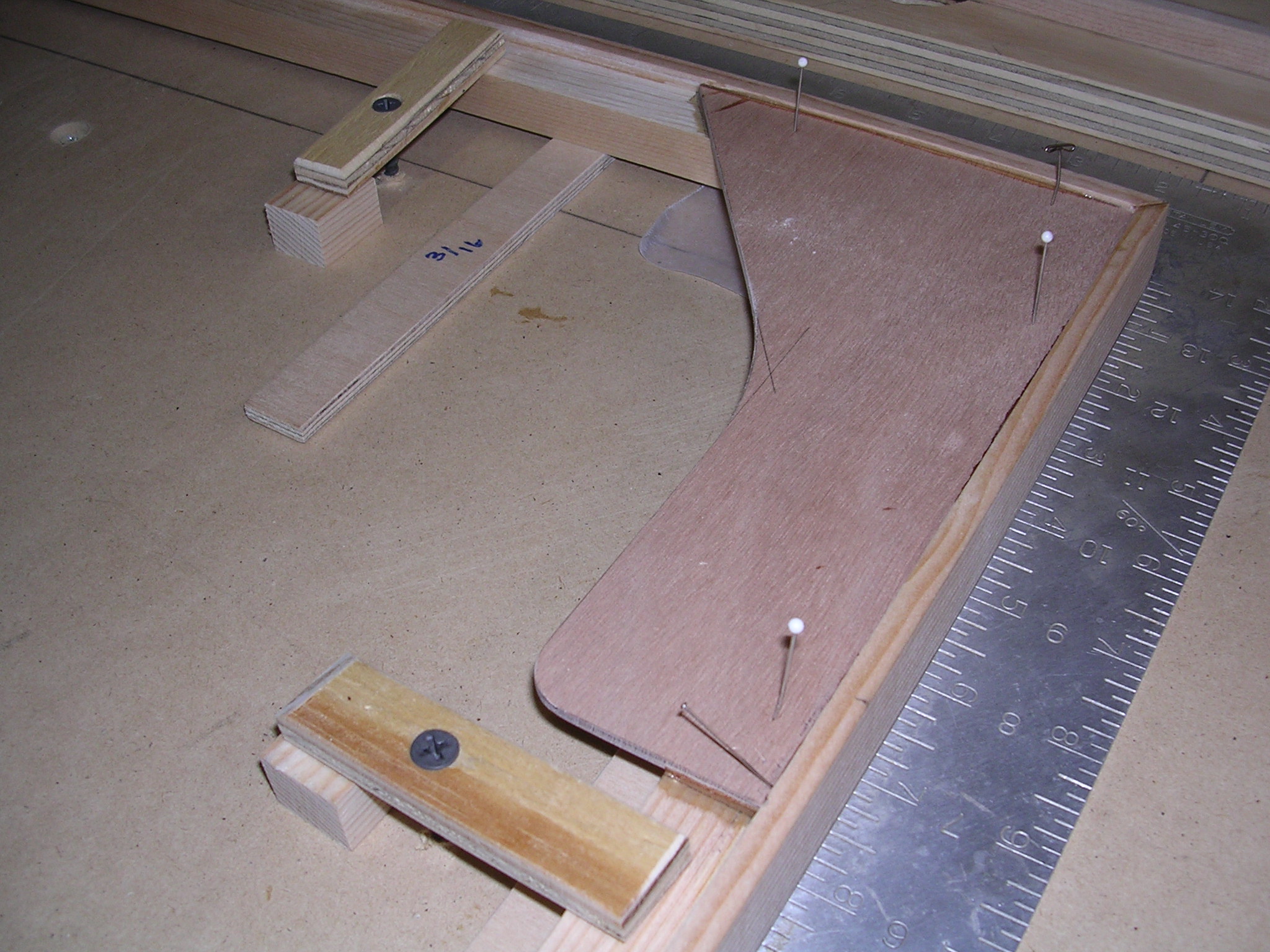
| CONSTRUCTION PHOTOS (Tail Group, Spars &
Ribs) |
 |
 |
 |
 |
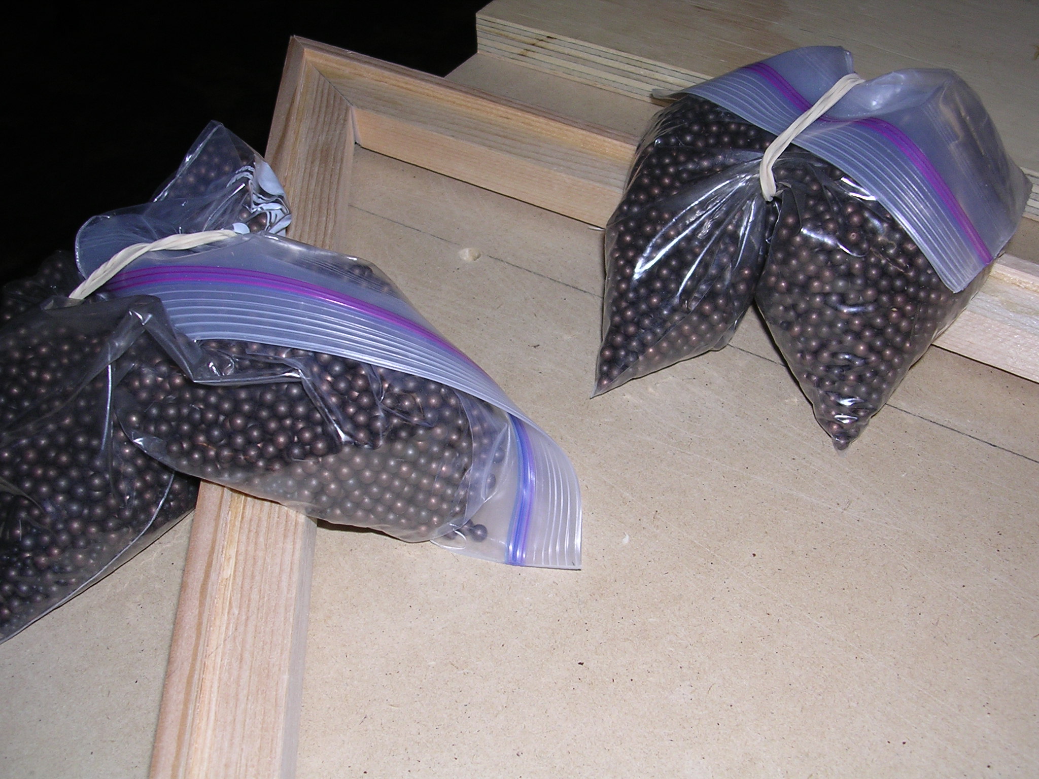
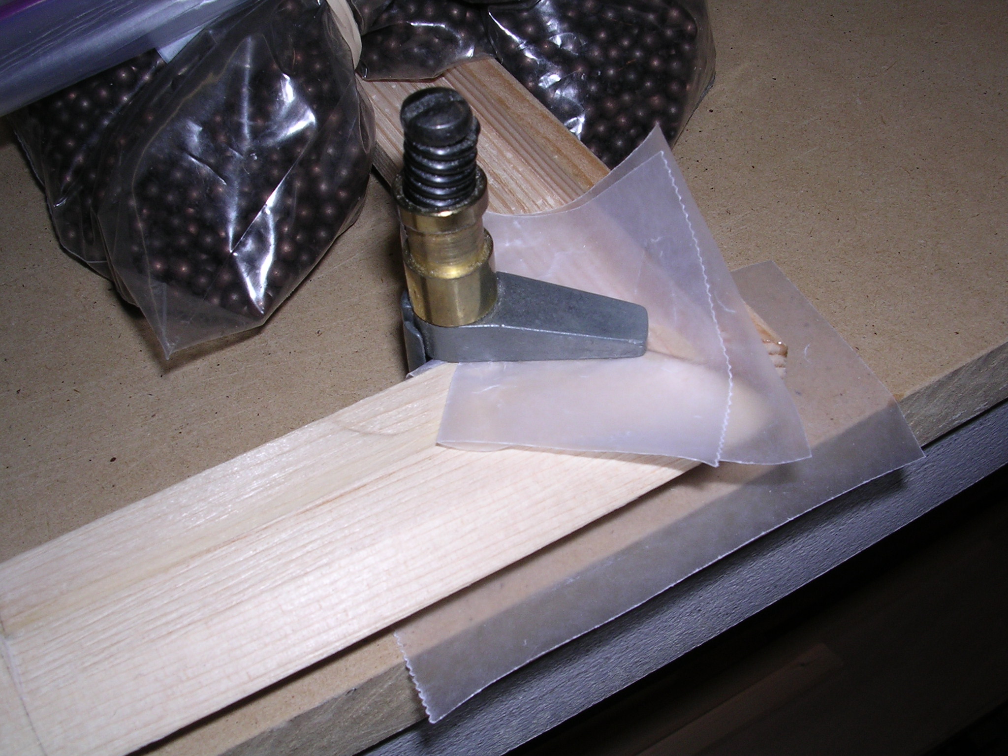
| Right elevator |
Right elevator |
Shot weights |
Right elevator |
|
|
|
|
|
|
|
|
 |
 |
 |
 |
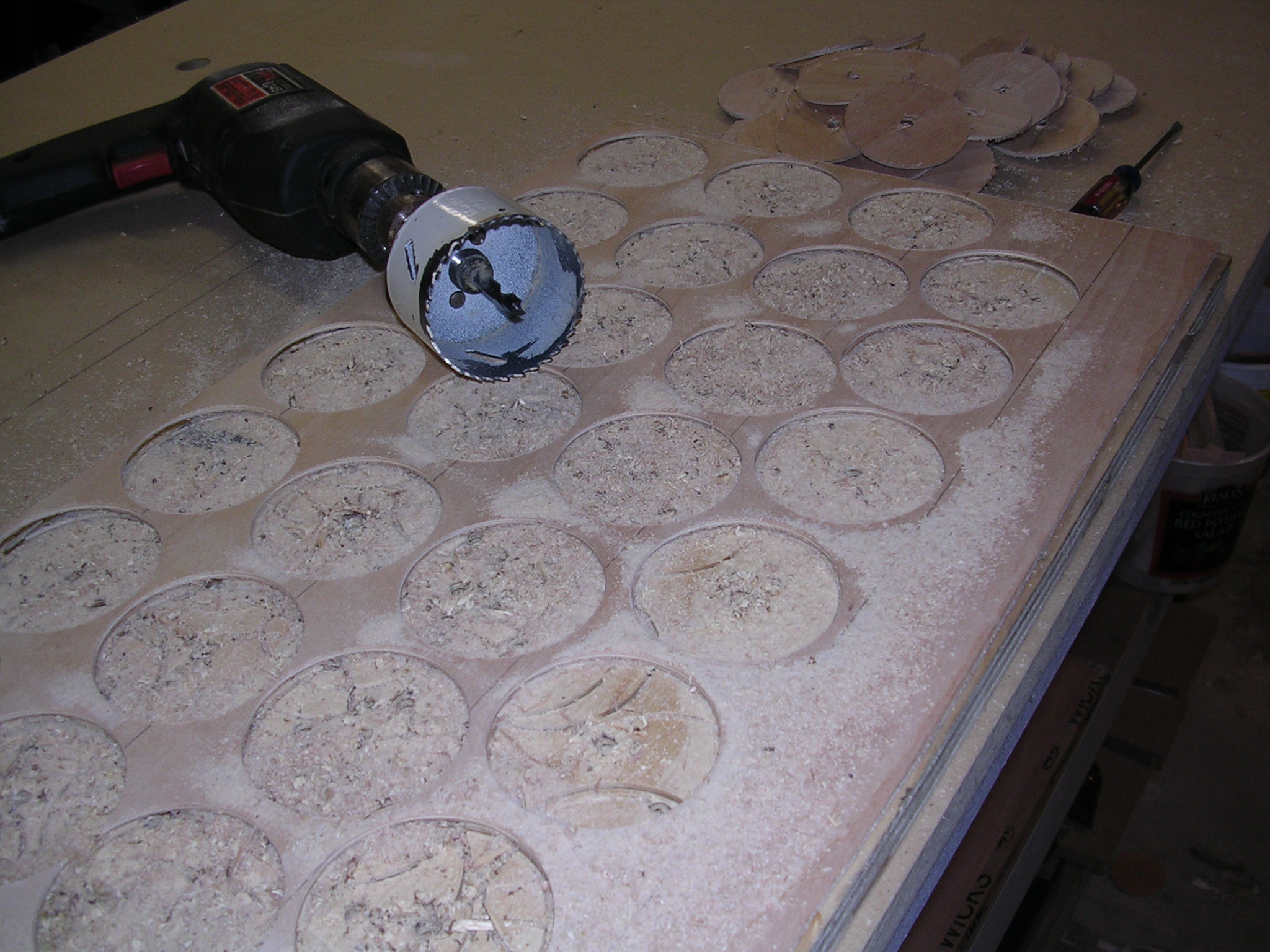
| Slow but sure! 11-05 |
2 1/2" hole-saw |
Sand on drill press |
Cut out for hinge |
 |
 |
 |
 |
| V Stab tip |
Getting closer |
Ribs |
H Stab and Elev |
 |
 |
 |
 |
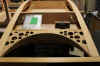
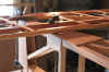
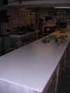
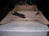
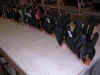
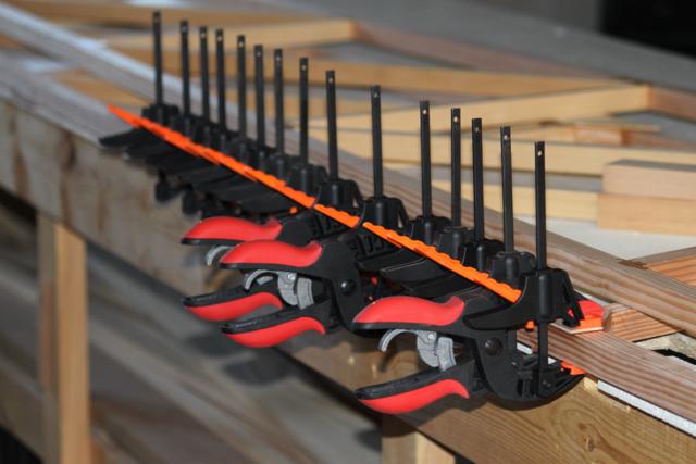
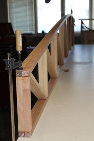
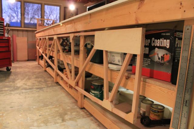
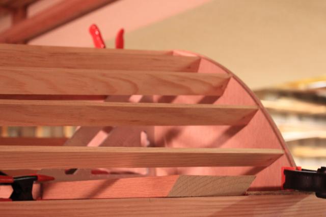
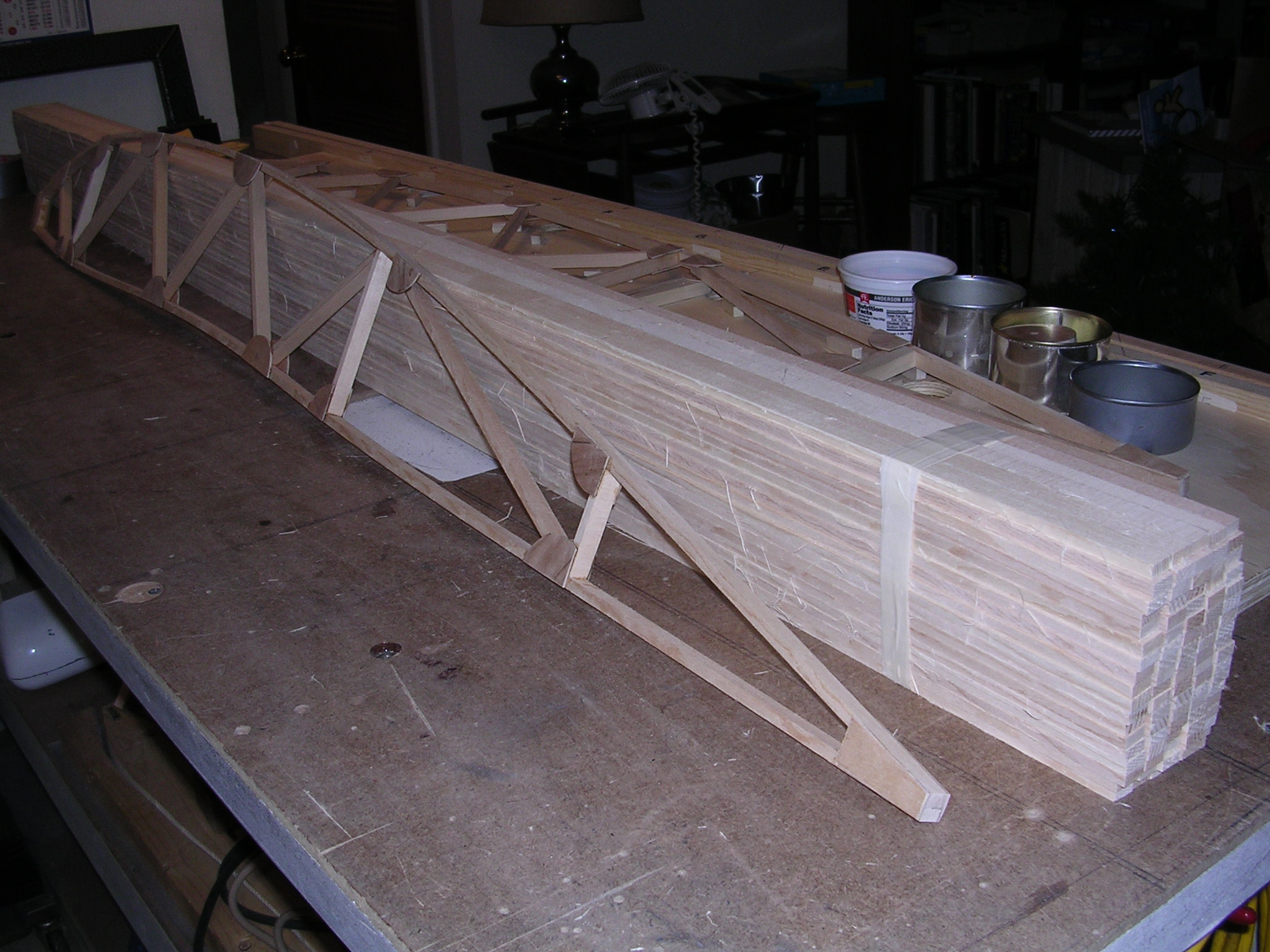
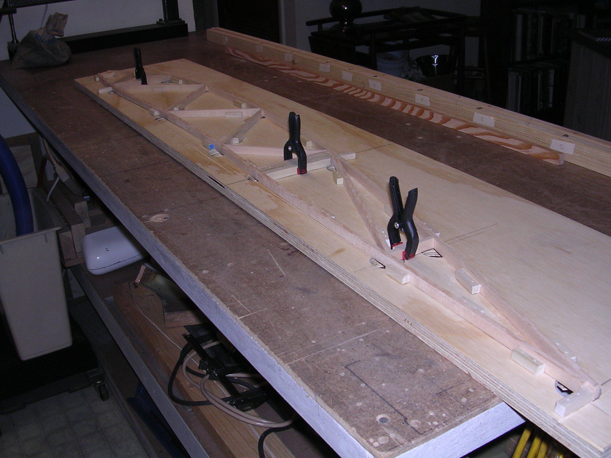
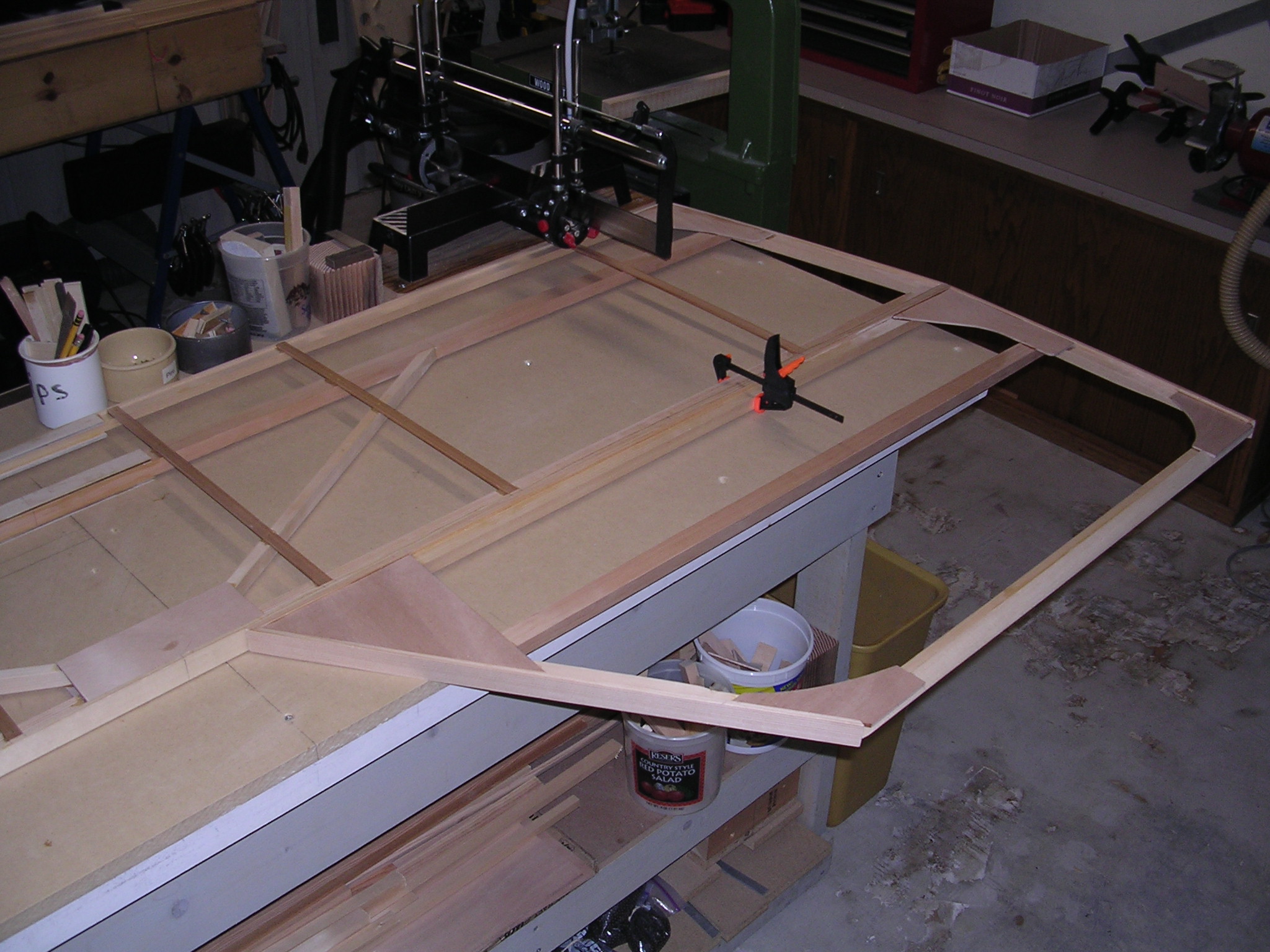
| New bench for fuselage |
End ribs w/uprights |
Ribs done!!! |
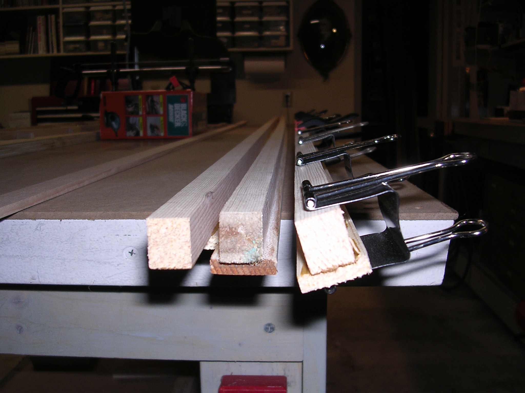
Web & cap stock |
 |
 |
 |
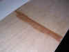 |
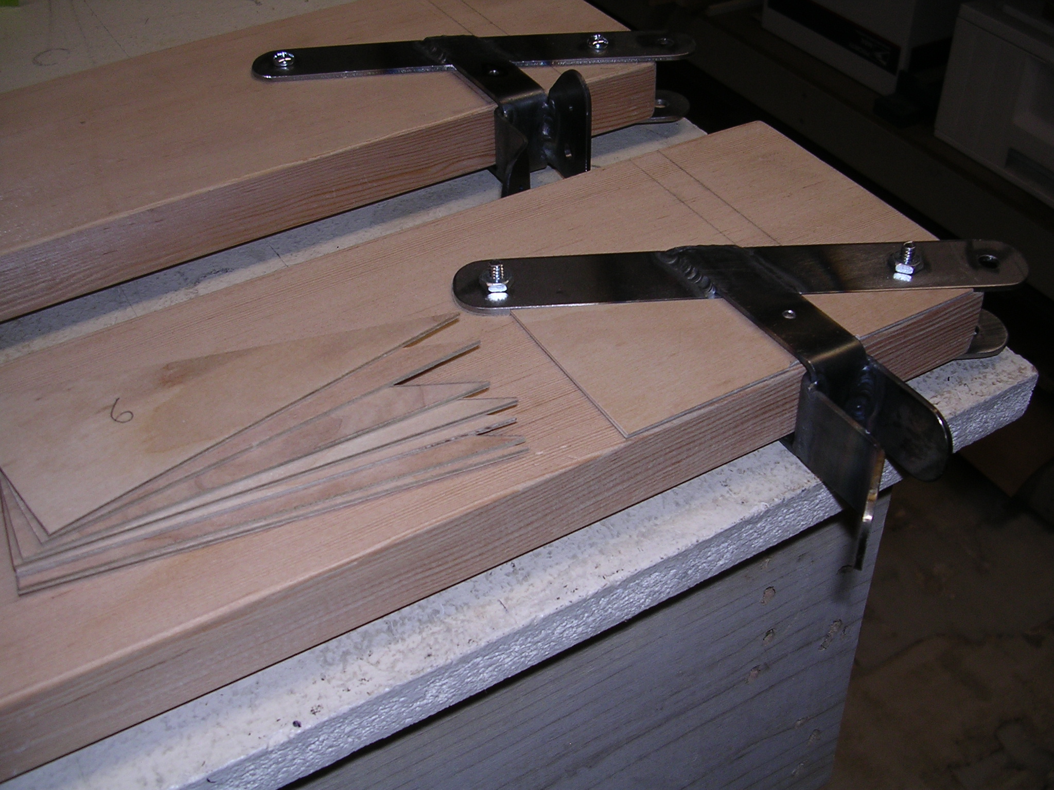
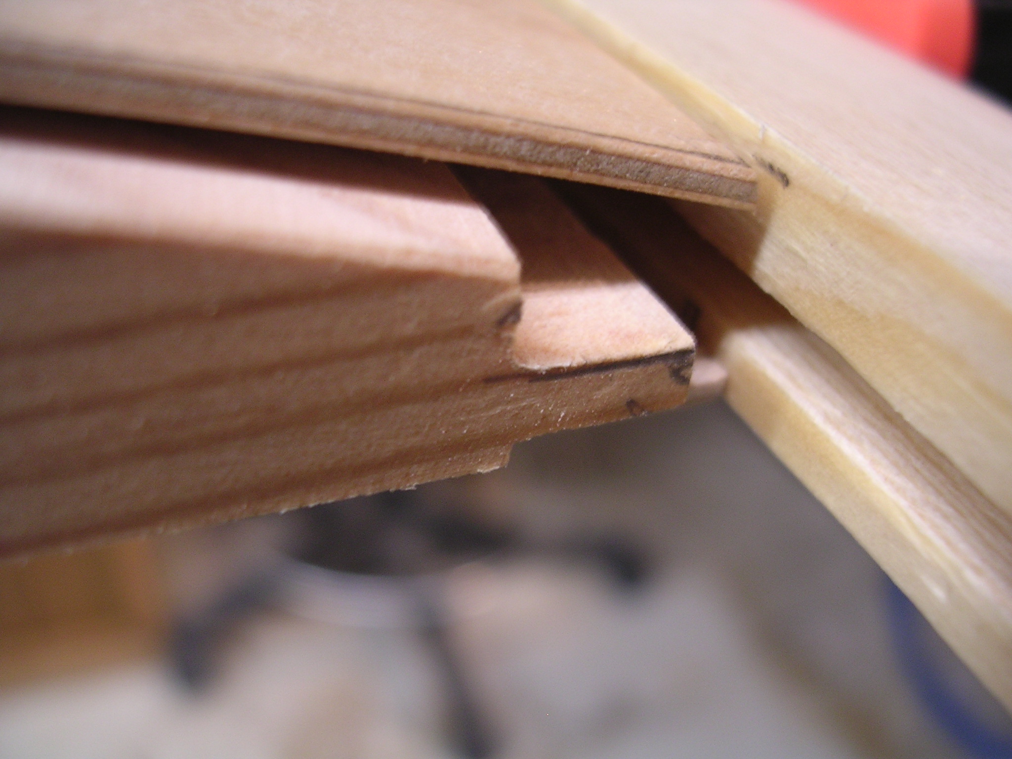
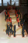
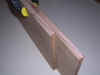
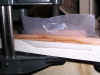
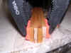
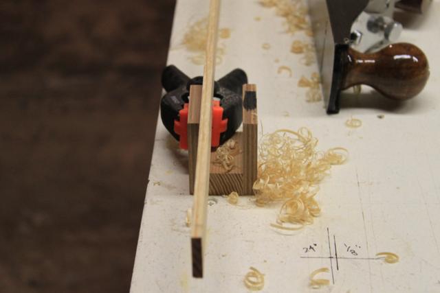
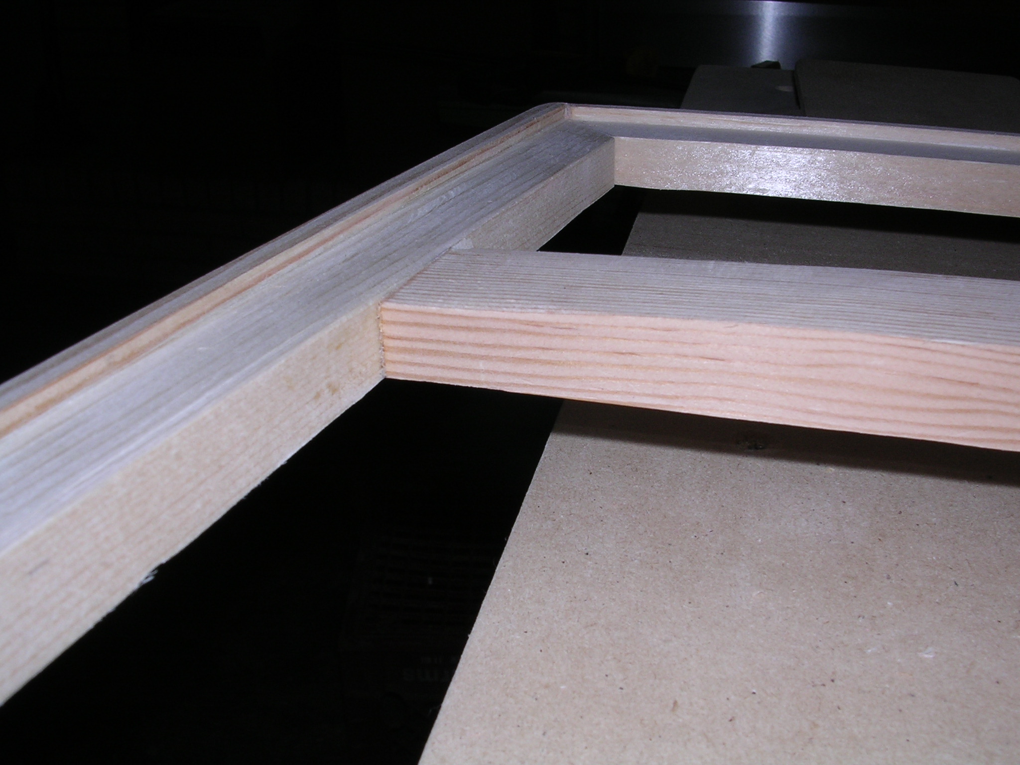
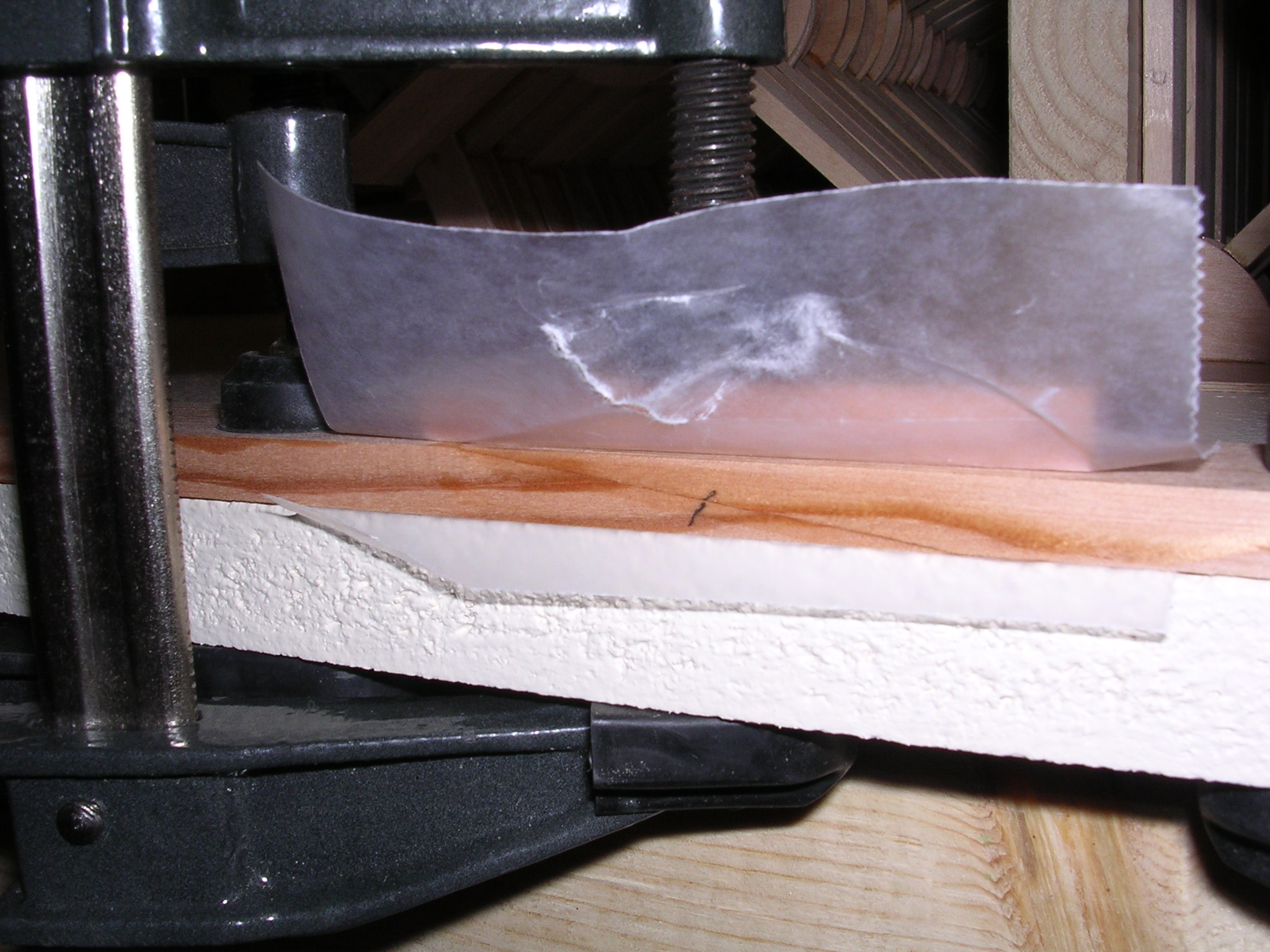
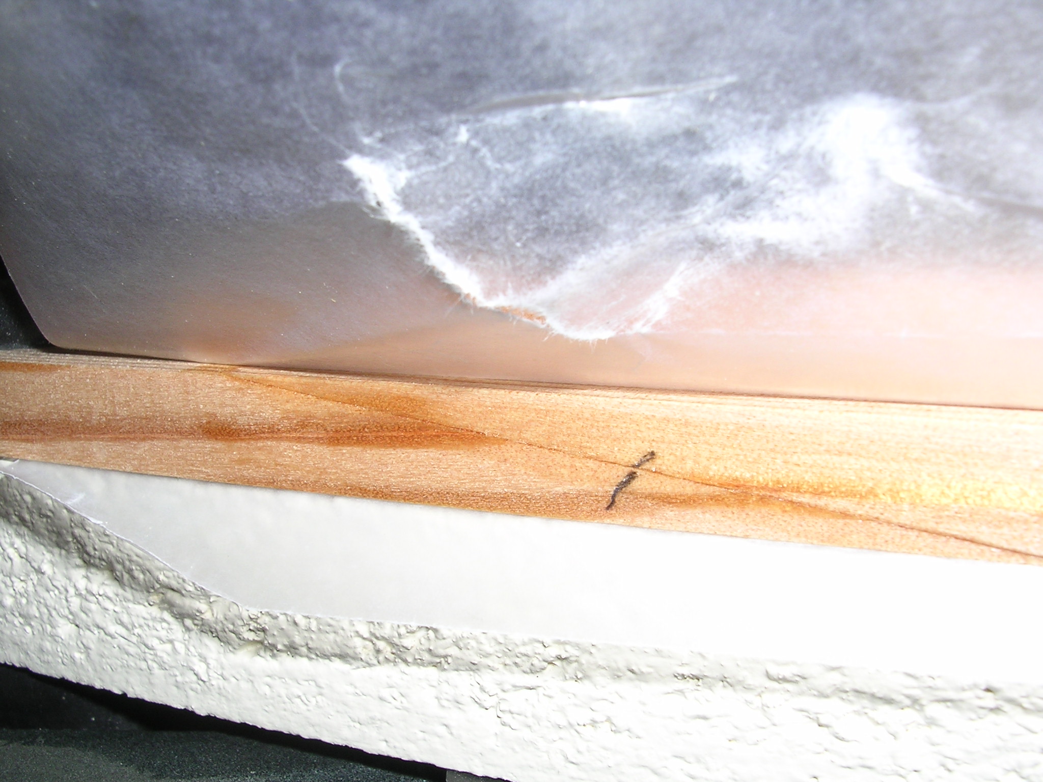
| 1/12 scarf for web |
Ready to glue |
Top one done, nice! |
Pretty good joint |
 |
 |
 |
 |
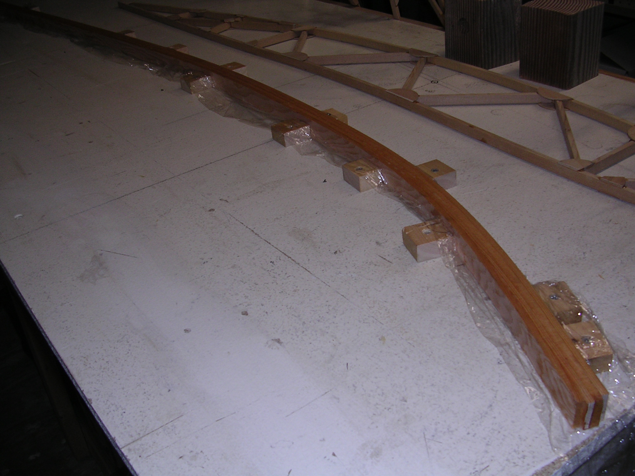
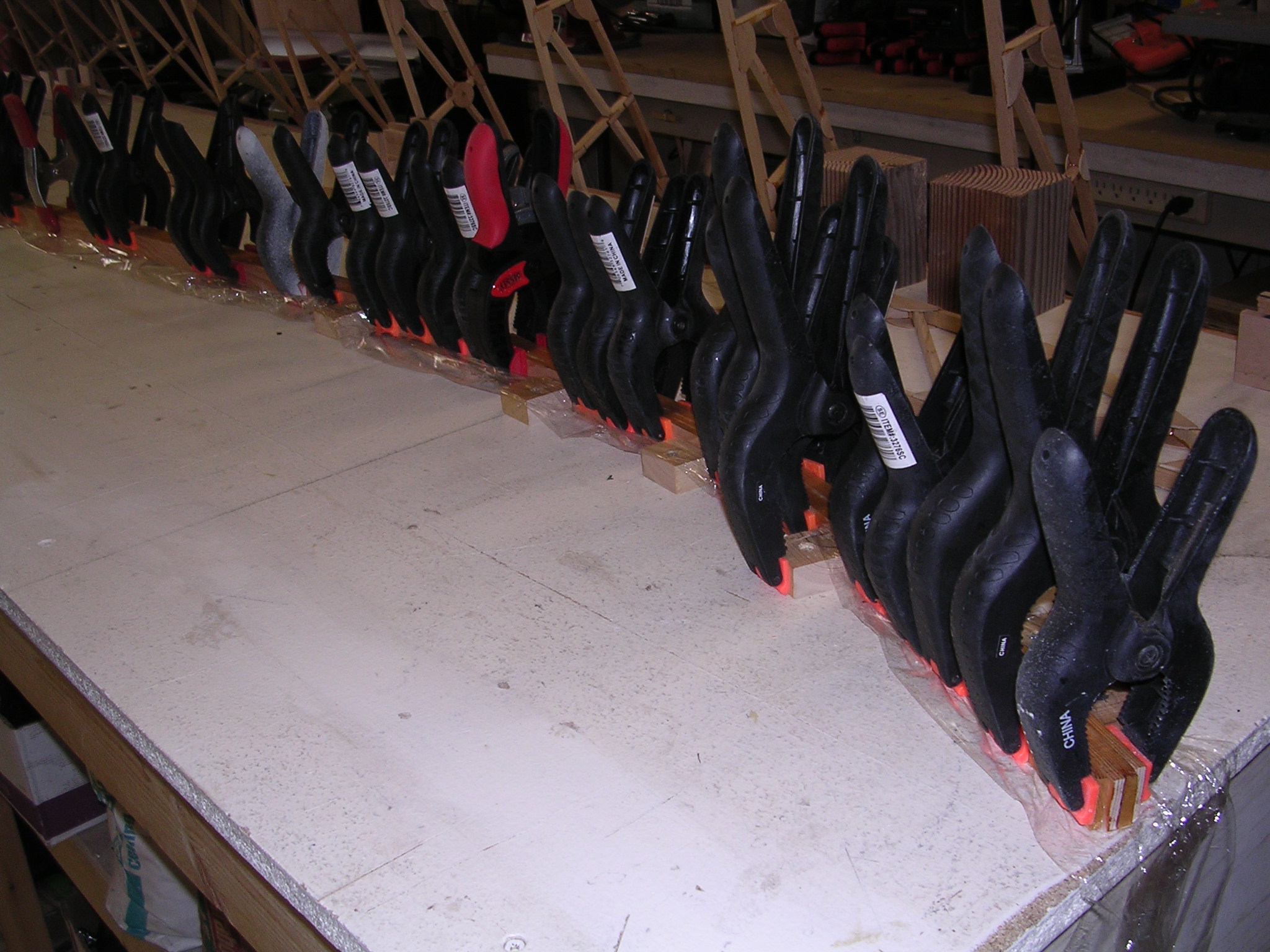
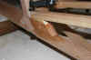
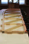
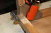
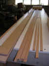
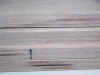
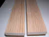
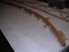
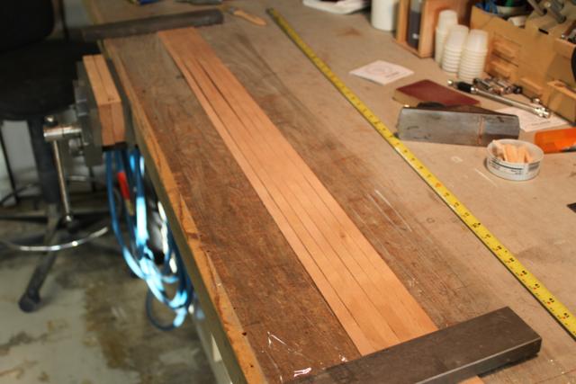
| Fir stock for caps |
Ripping & planing |
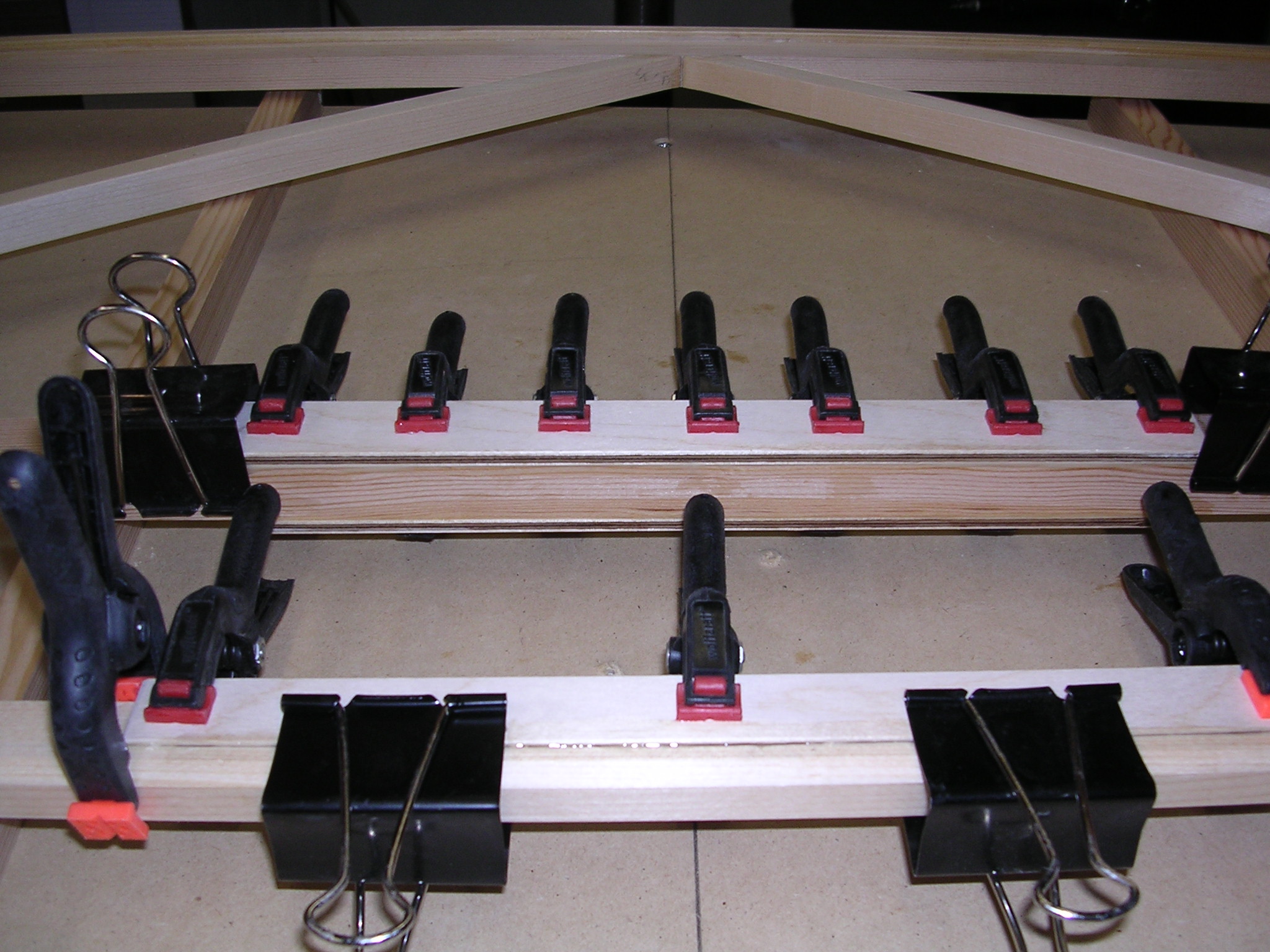
Many blades later |
Gluing |
 |
 |
 |
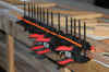
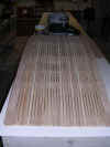
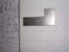
![SparSketch[2].jpg (426912 bytes)](SparSketch2_small.jpg) |
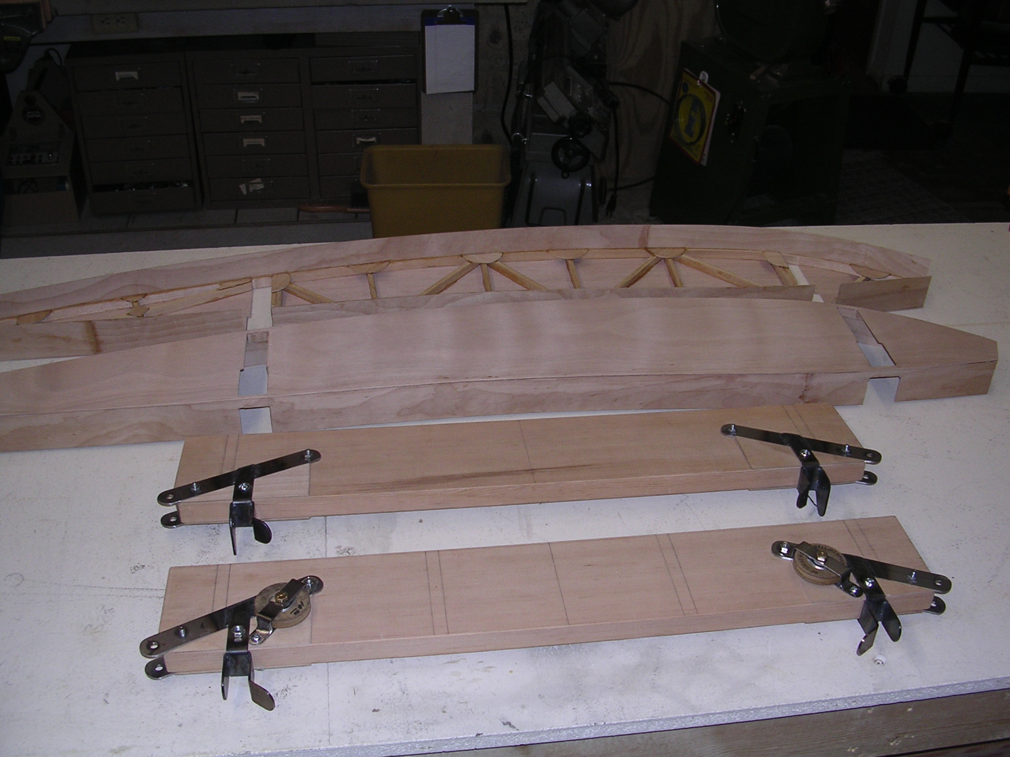
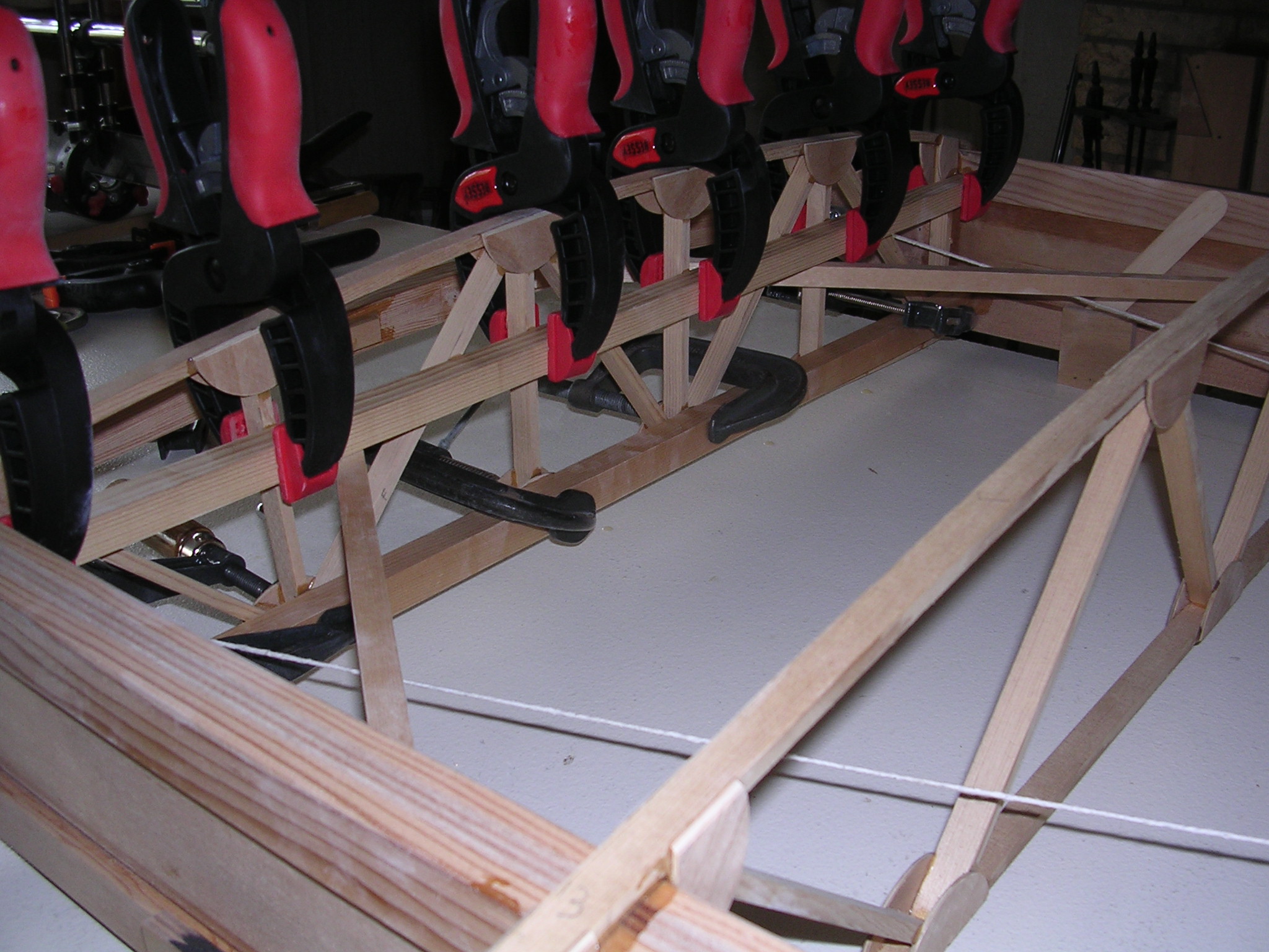
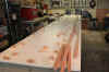
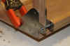
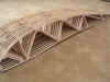
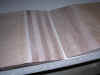
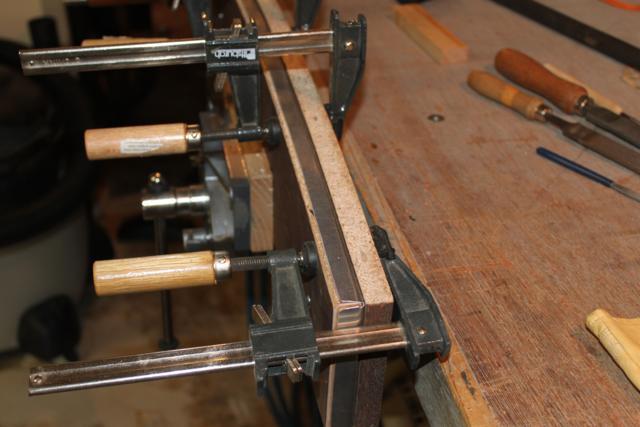
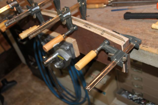
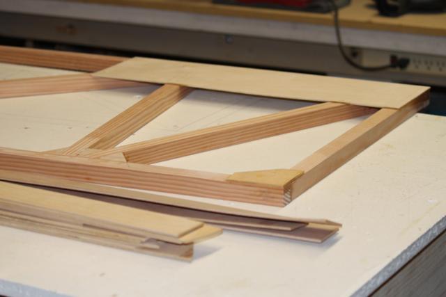
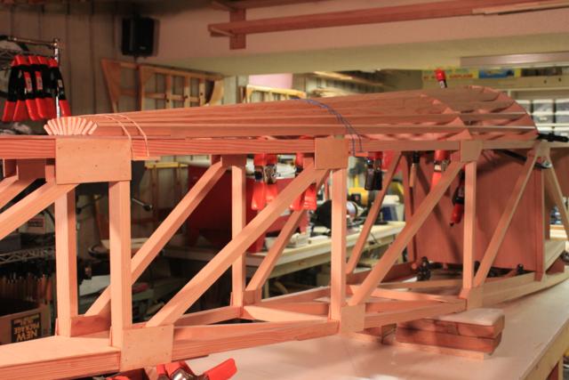
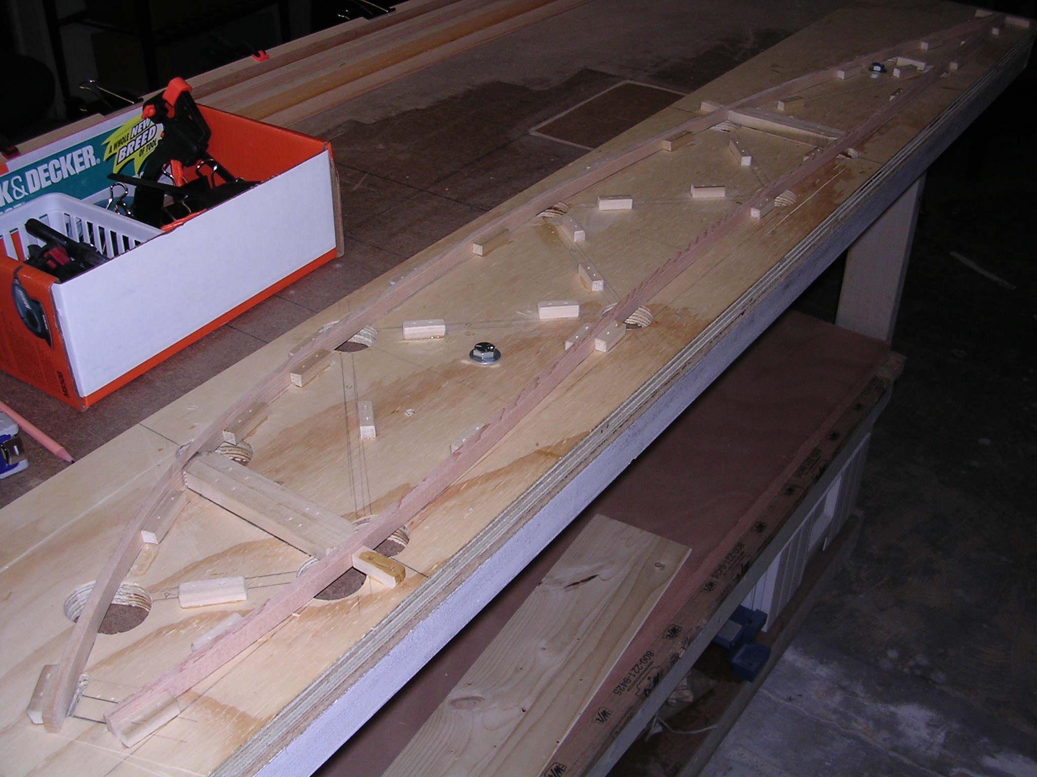
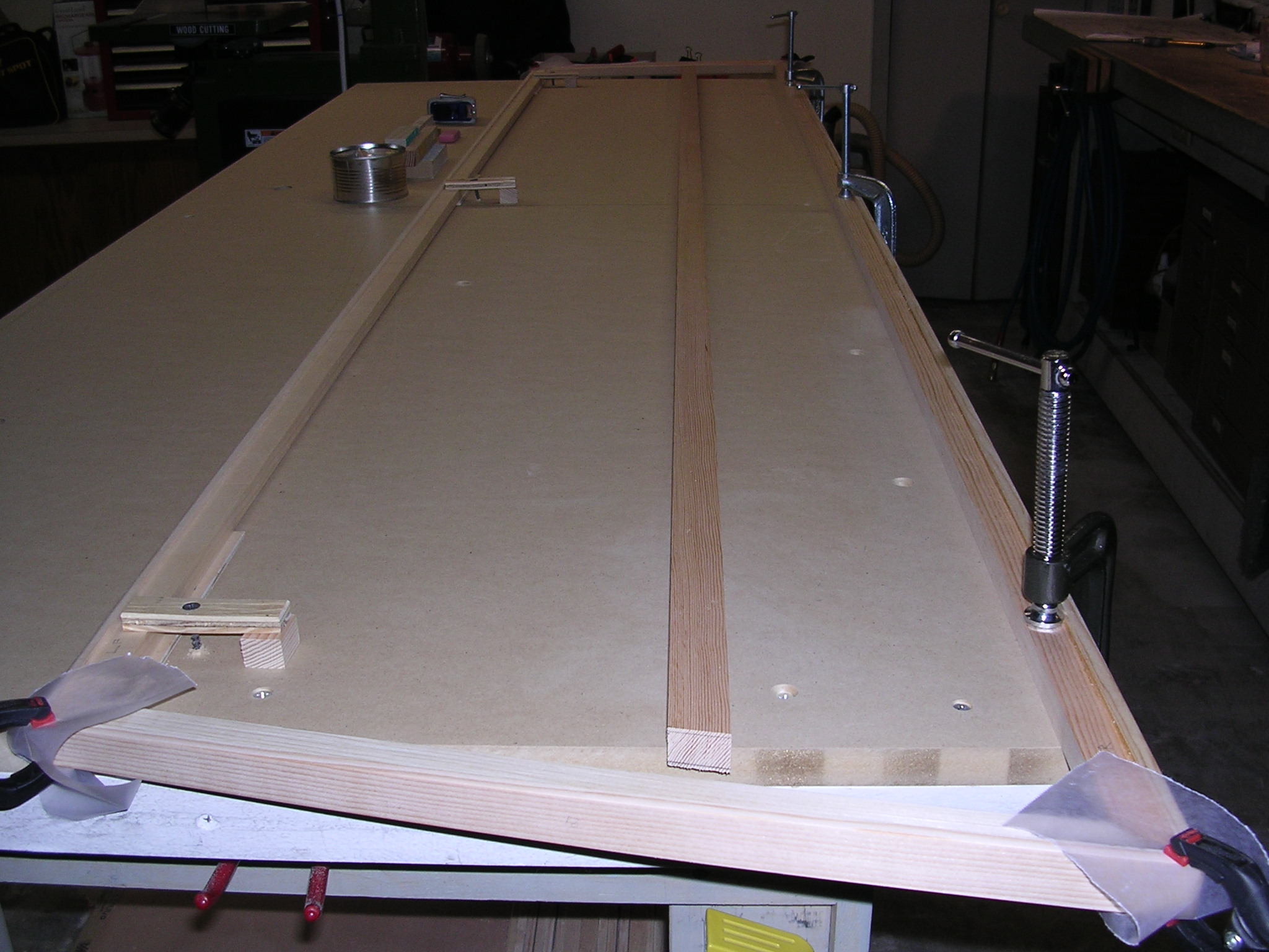
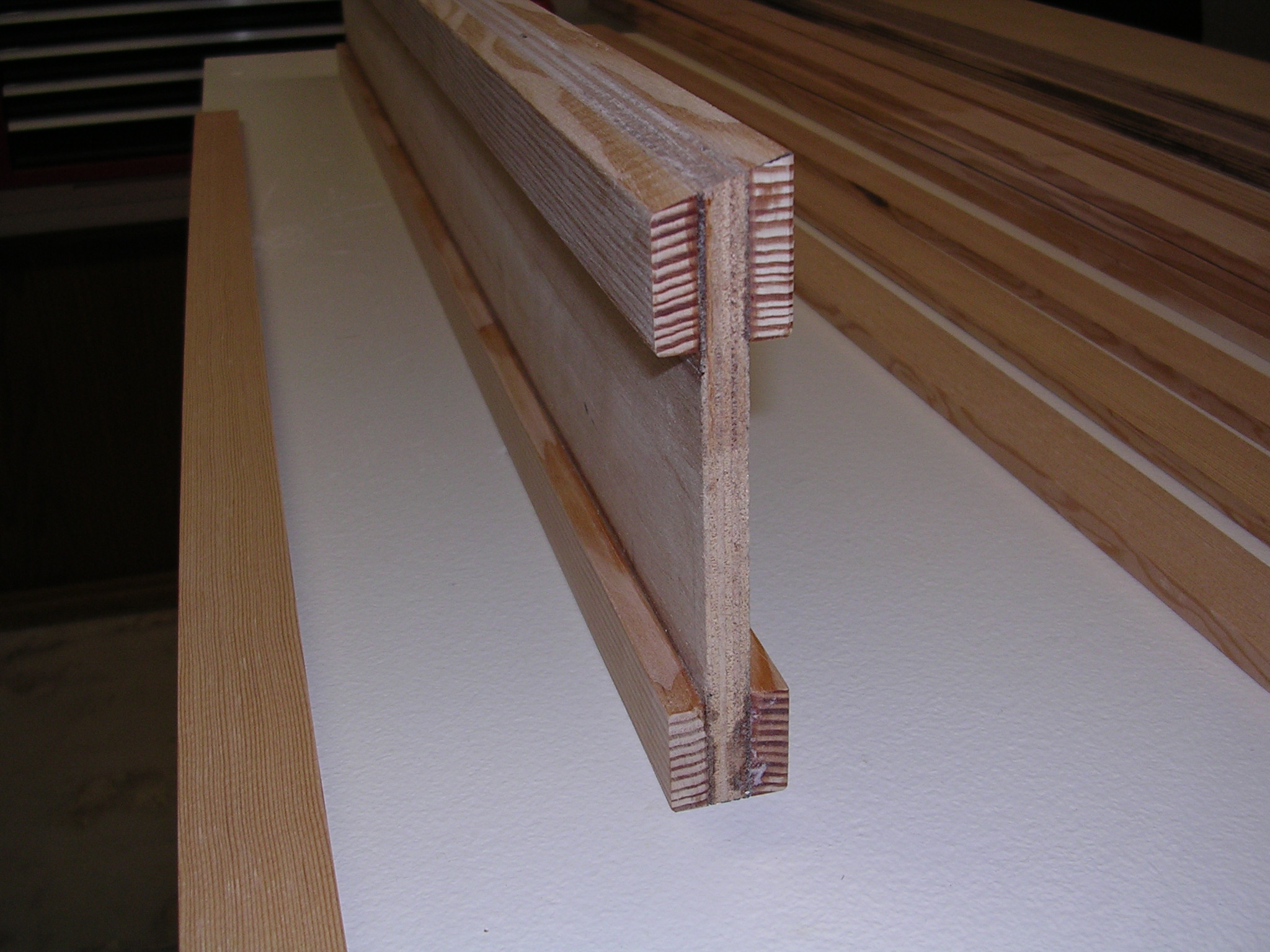
| More scarfs, 1 p/cap |
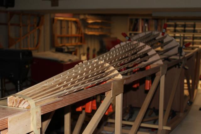
Trial spars, 9mm, 7 ply webs,
5/16x1"+ caps |
Spar drawing |
 |
 |
 |
 |
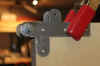
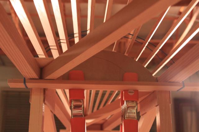
| C-Section started |
C-Section strap |
Gluing 2" rib cap |
L-rear cabane fitting |
 |
 |
 |
 |
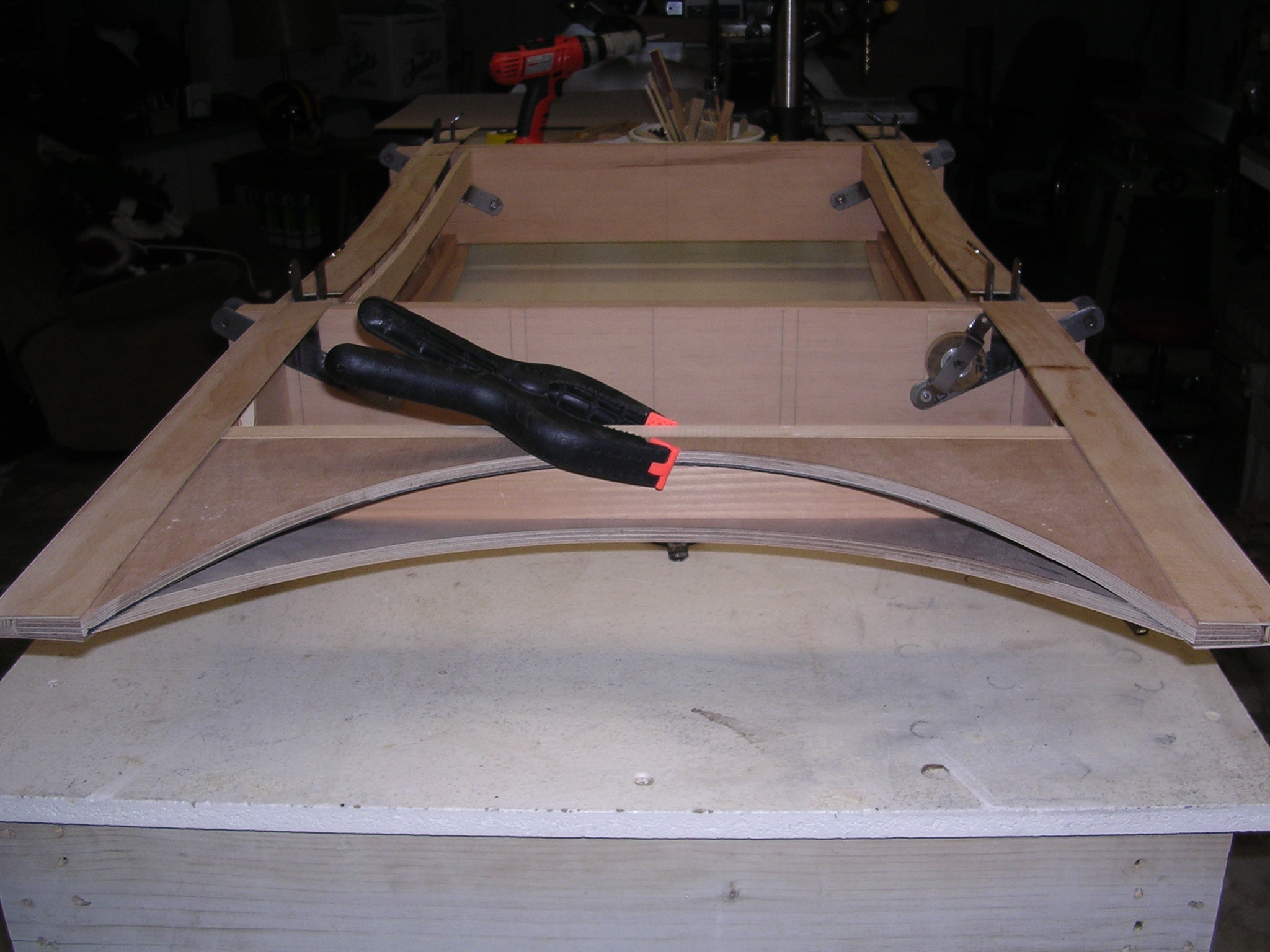
| Starting 2nd bend |
Makeshift brake |
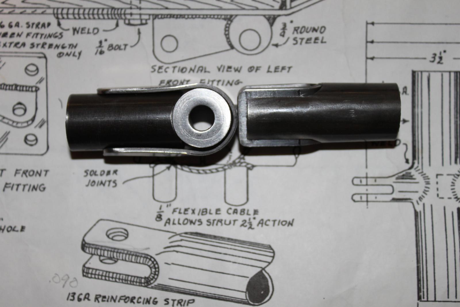
Front cabane fitting |
Cabane fitting & strap |
 |
 |
 |
 |
| Ready to weld |
Front fitting |
Rear Fitting |
Elev & rudder horns |
 |
 |
 |
 |
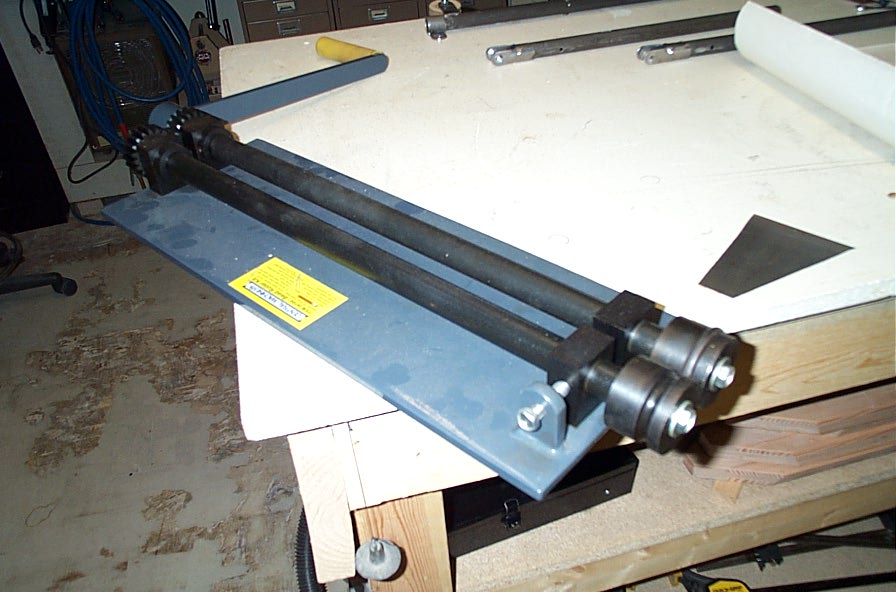
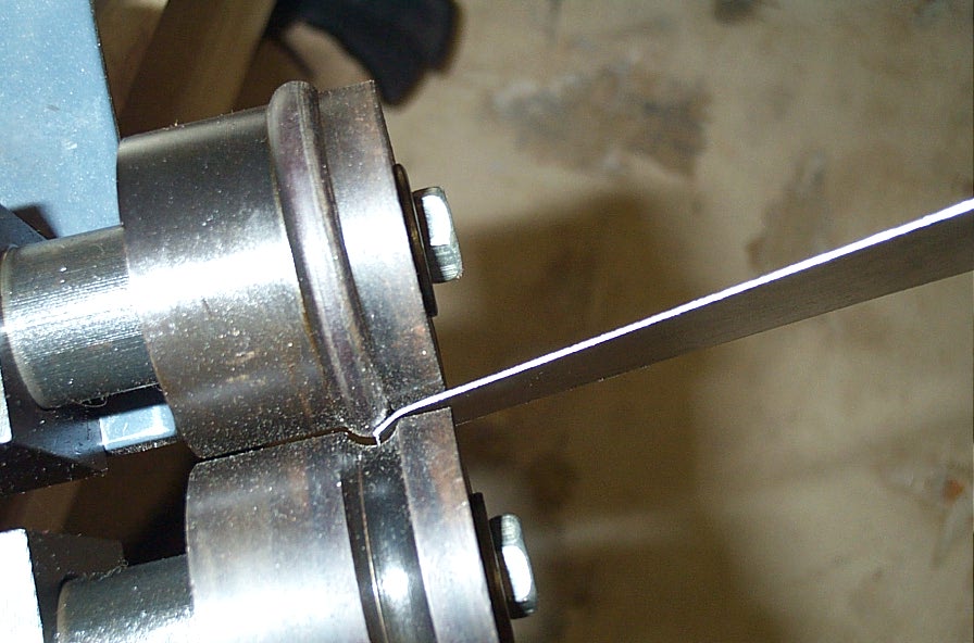
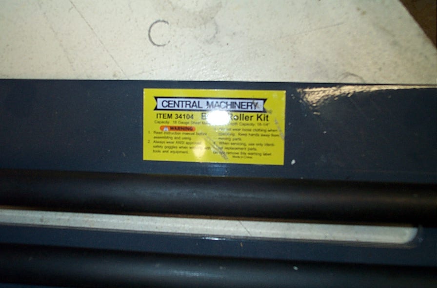
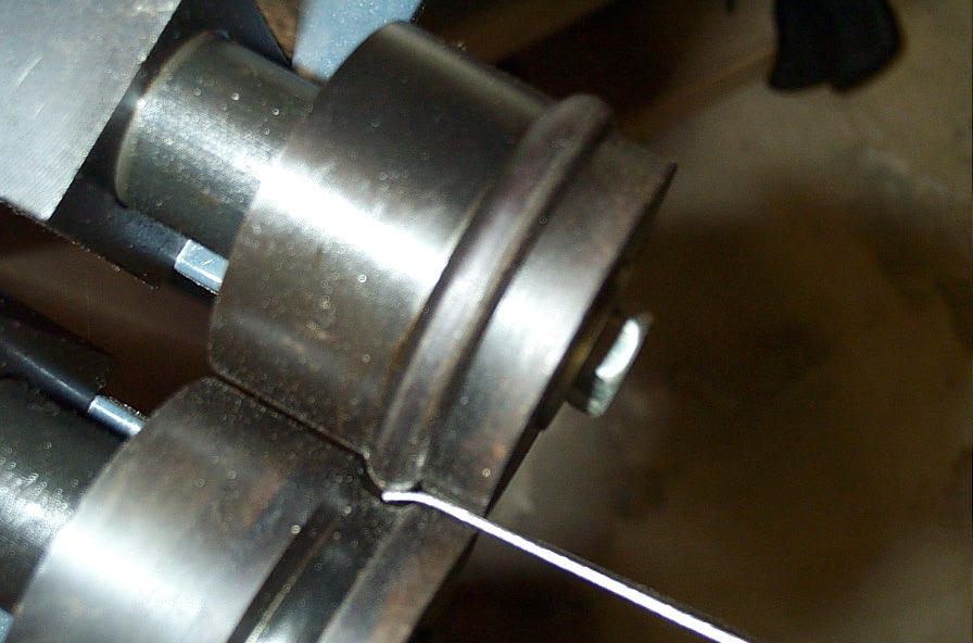
| Bead roller for horns |
Larger roller |
Harbor Freight 34104 is 18" |
12" model would be big enough |
 |
 |
 |
 |
| Aileron horns |
Horn braces |
Rudder horn brace |
Great weld! |
| Special thanks to Jerry Grogan for his
expert welding on the critical parts! |
 |
 |
 |
 |
| Control horn (oversized) |
Welded horns |
Remade both of these |
 |
 |
 |
 |
| Sticks tacked, will leave final welds
to pro |
Center bearings |
Outer bearings |
Wingtip braces |
 |
 |
 |
 |
| C-section trial fit |
Drilling straps |
Strap ply, don't glue yet |
Pedals started |
 |
 |
 |
 |
| Didn't use, made thicker |
C-section cut-out |
Straps done! |
More C-section |
 |
 |
 |
 |
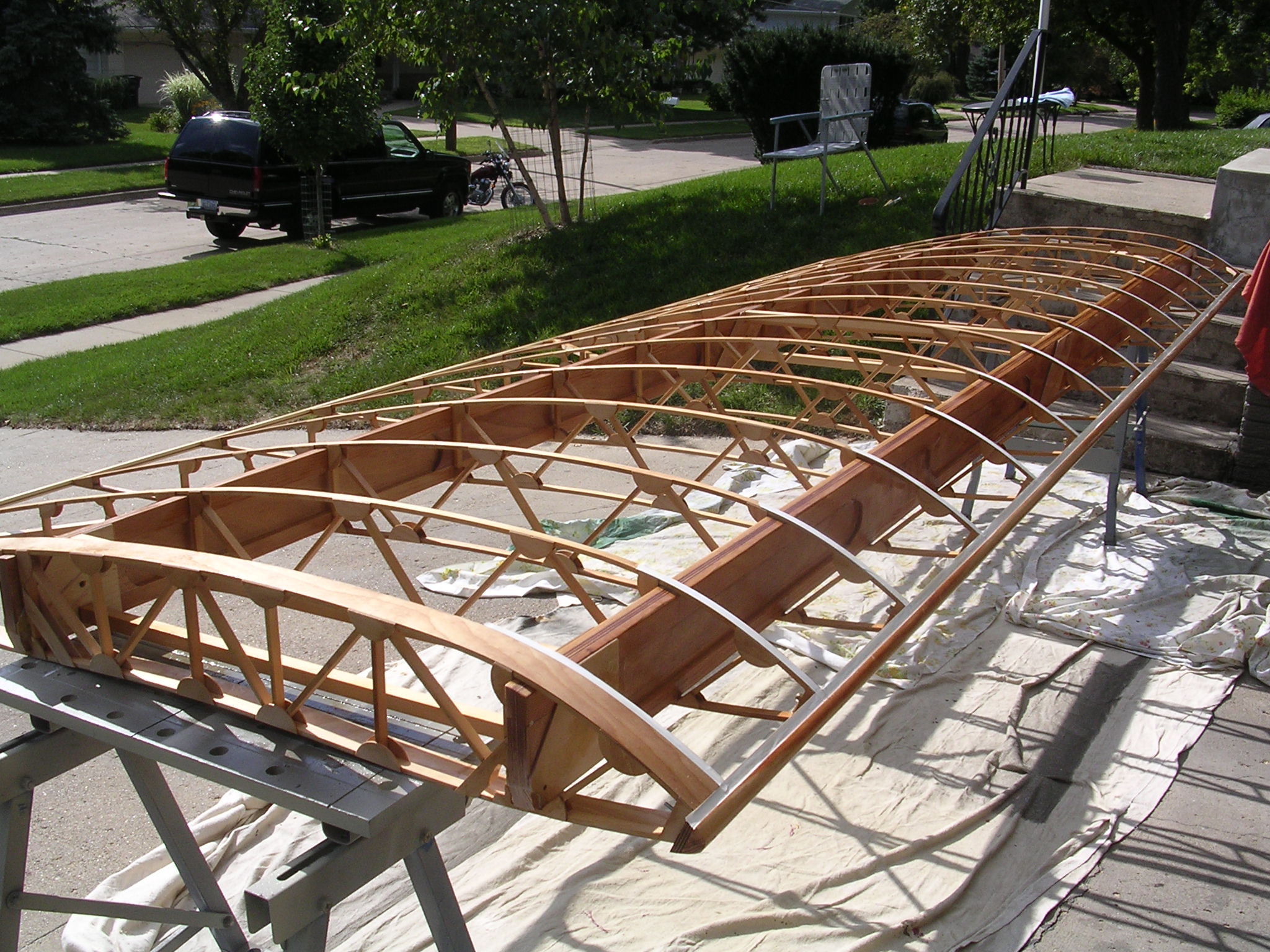
| Left wing started |
From outboard end |
Wingtip Glued |
Four fir plys |
 |
 |
 |
 |
| Clamped tip |
Gluing root doubler |
Comp strut cut-outs |
Comp struts test fit |
 |
 |
 |
 |
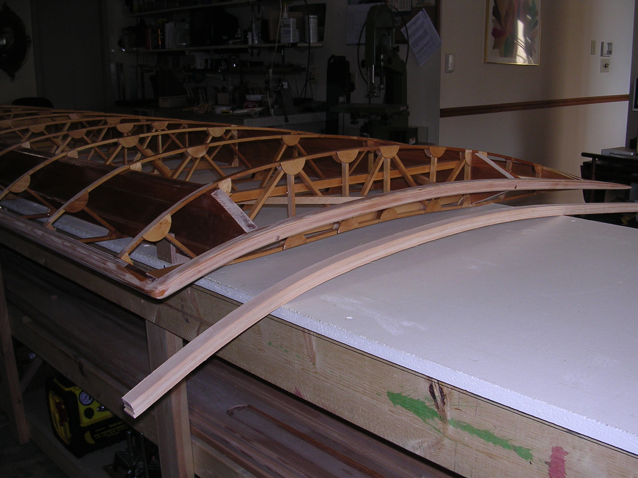
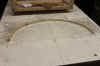
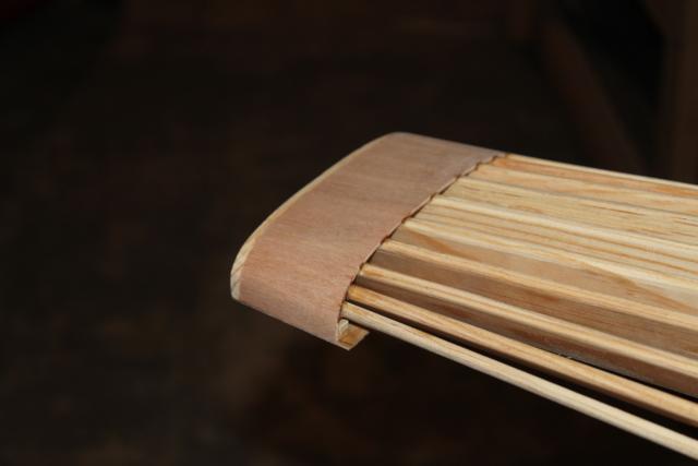
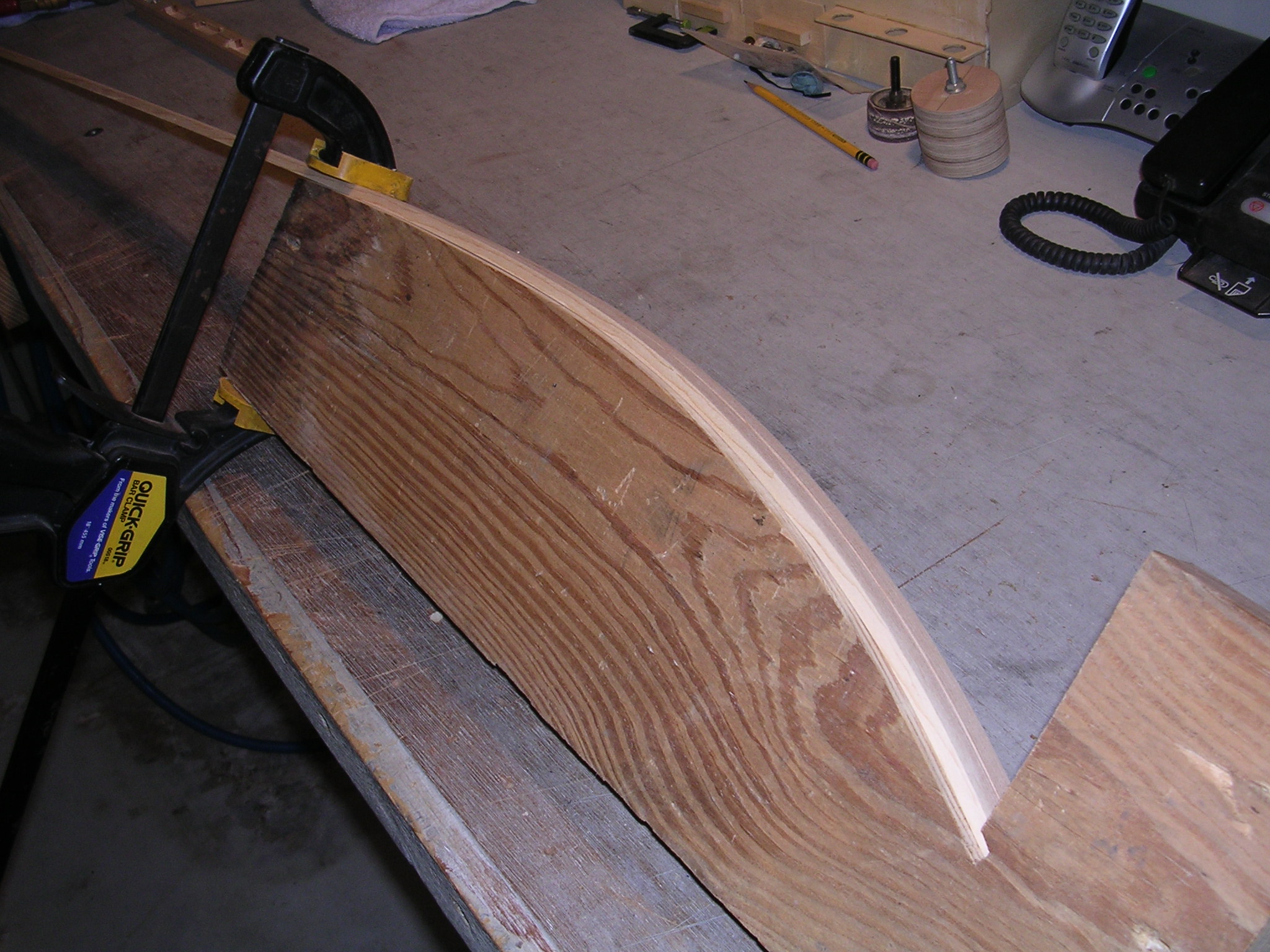
| Scarfing 1/16" LE |
Root rib cut-outs |
Additional brace |
Aileron end |
 |
 |
 |
 |
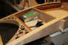
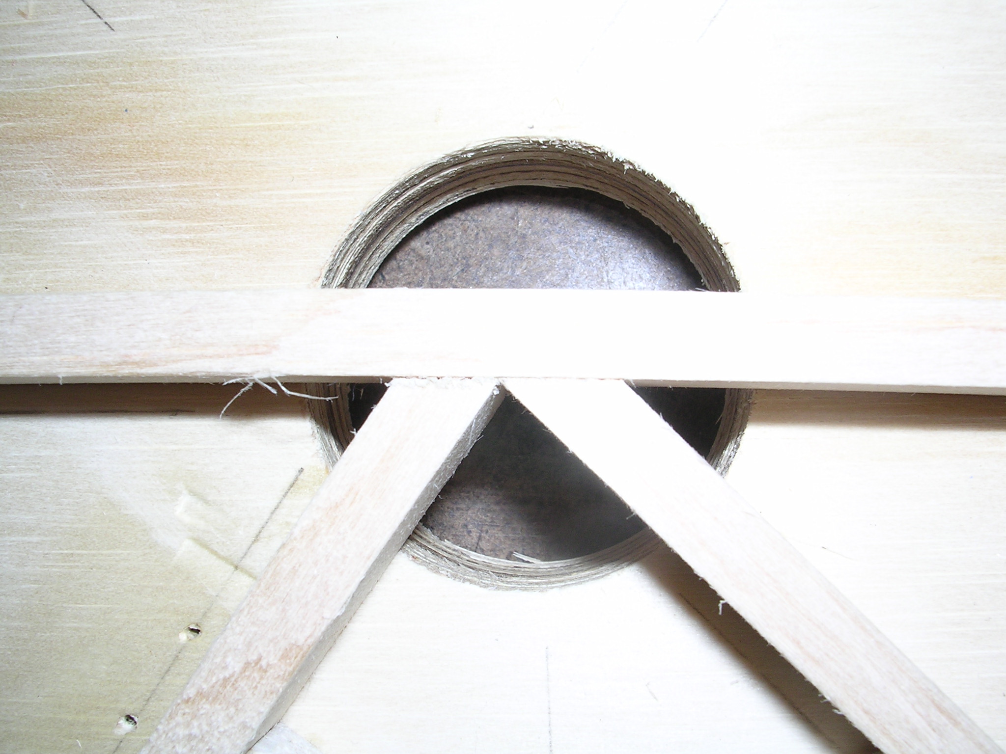
| Cross brace seat |
Must be cut out |
C-section-L-wing test |
Test fit |
 |
 |
 |
 |
| Cutout progressing |
Trailing edge cut out |
X-tra comp struts wing tip |
First coat varnish |
 |
 |
 |
 |
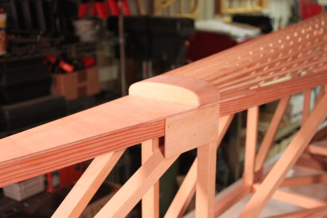
| 2nd wingtip formed |
Mounting hardware |
More hardware |
Tip brace-drag wire |
 |
 |
 |
 |
| Fitting aileron hinge |
Nutplates |
Aileron hinge |
Wow it works |
 |
 |
 |
 |
| Inboard end |
Need more angle on both bearings |
Bottom |
Root rib braces-rear bay |
 |
|
|
|
| Inboard rear bay |
|
|
|
|
|
|
|
|
|
|
|
|
|
|
|
|
|
|
|
|
|


![SparSketch[2].jpg (426912 bytes)](SparSketch2.jpg)